Filter cartridge

a filter cartridge and filter cartridge technology, applied in the field of filter cartridges, can solve the problems of excessively reducing the inflow of fluid, affecting the design of the filter cartridge, slow, laborious and therefore rather expensive, and achieve the effect of simple, rational and relatively inexpensiv

Active Publication Date: 2014-02-25
UFI FILTERS SPA
View PDF6 Cites 1 Cited by
  • Summary
  • Abstract
  • Description
  • Claims
  • Application Information

AI Technical Summary

Benefits of technology

[0014]An aim of the present invention is therefore to obviate the above-mentioned drawbacks in the prior art, with a solution which is simple, rational and relatively inexpensive.

Problems solved by technology

During use, it can happen that the fluid to be filtered encounters excessive hydraulic resistance to passage across the filter wall, which excessively reduces the inflow of the fluid to the devices located downstream of the filter.
Although this arrangement facilitates the realisation of the by-pass valve, it considerably limits the design of the filter cartridge, as the central zone of the support plates is that which generally also bears the engaging means with the filter casing as well as being the zone which exhibits the openings destined to place the internal volume of the filter wall in communication with the inlet or the outlet of the filter.
Though effective from the functional point of view, this constructional form introduces some important drawbacks.
A first drawback is that in a case of malfunctioning of the bypass valve, it is necessary to demount and replace the whole support plate, by means of an operation which is often slow, laborious and therefore rather expensive.
A further drawback is that the bypass valve has also to be assembled together with the filter cartridge, which requires adopting mounting procedures which are dedicated for each type of filter cartridge produced, and thus reducing the possibility of obtaining advantageous economies of scale.

Method used


Image

  • Filter cartridge
  • Filter cartridge
  • Filter cartridge

Examples


Embodiment Construction

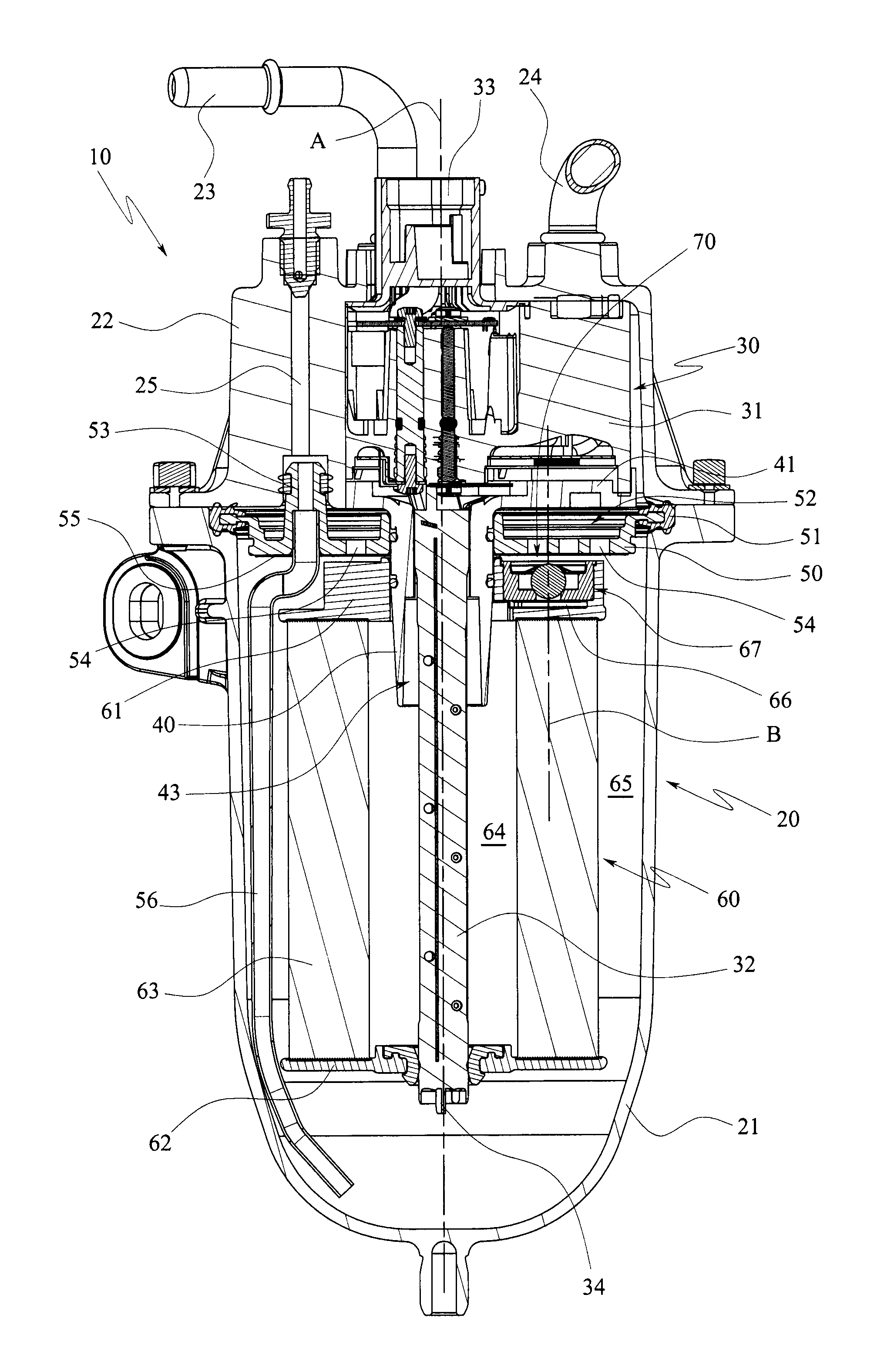
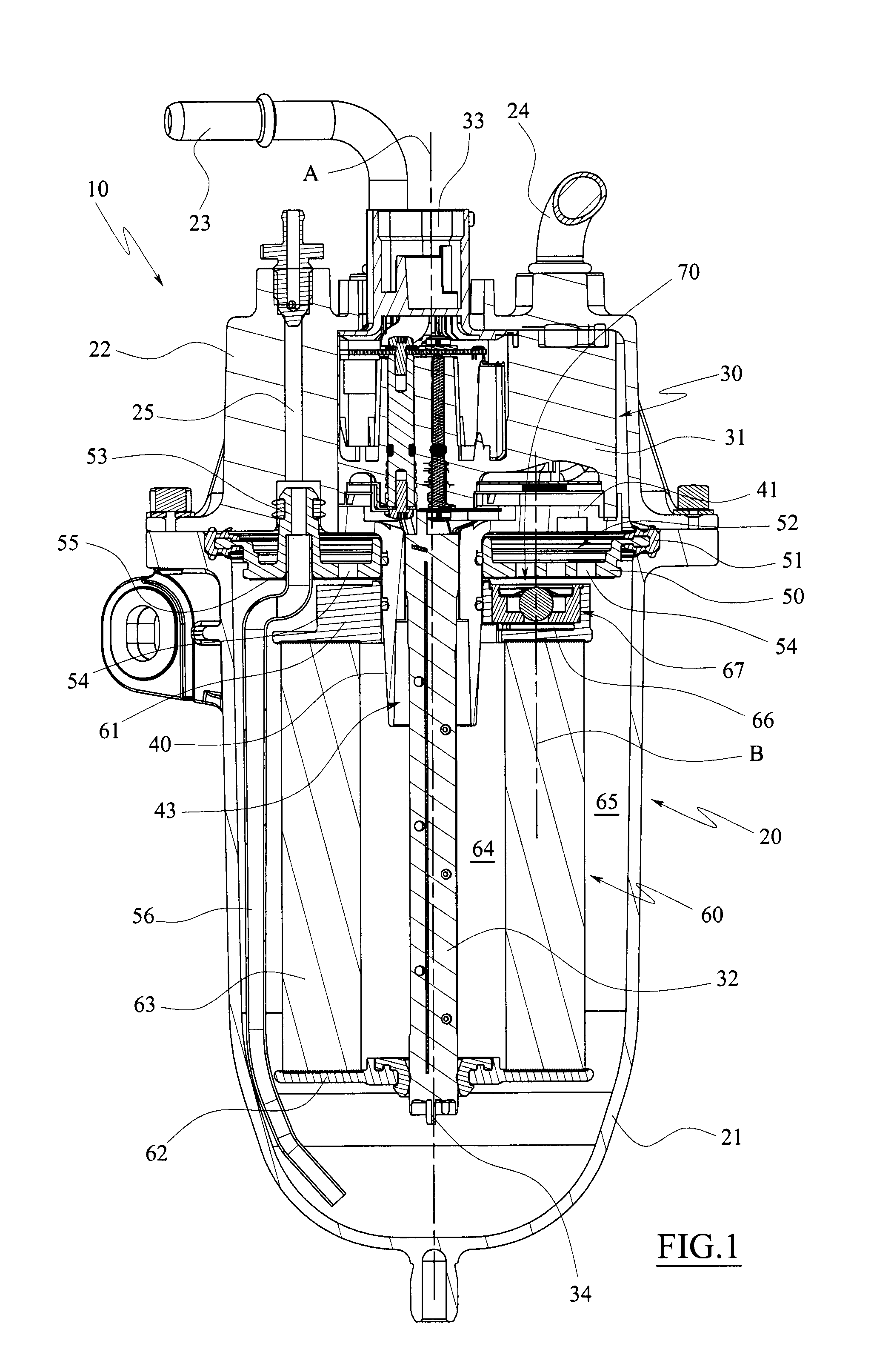
[0069]The filter 10 illustrated in FIG. 1 is a diesel filter destined to be applied in diesel engines, in particular diesel for motor cars, lorries, commercial vehicles or self-propelling work vehicles.

[0070]The filter 10 comprises an external casing, denoted in its entirety by 20, which is defined by a lower body 21 shaped as a beaker and an upper cover 22 destined to close the beaker body 21.

[0071]The cover 22 comprises an inlet conduit 23 for the diesel to be filtered, an outlet conduit 24 for filtered diesel and a discharge conduit 25 for the water which can be accumulated on the bottom of the beaker body 21.

[0072]A monolithic component 30 is housed internally of the casing 20, which comprises a broadened upper portion 31 which is housed in a corresponding seating afforded in the cover 22, and a lower stem portion 32 which is welded to the broadened portion 31 and develops axially in a downwards direction internally and centrally of the beaker body 21.

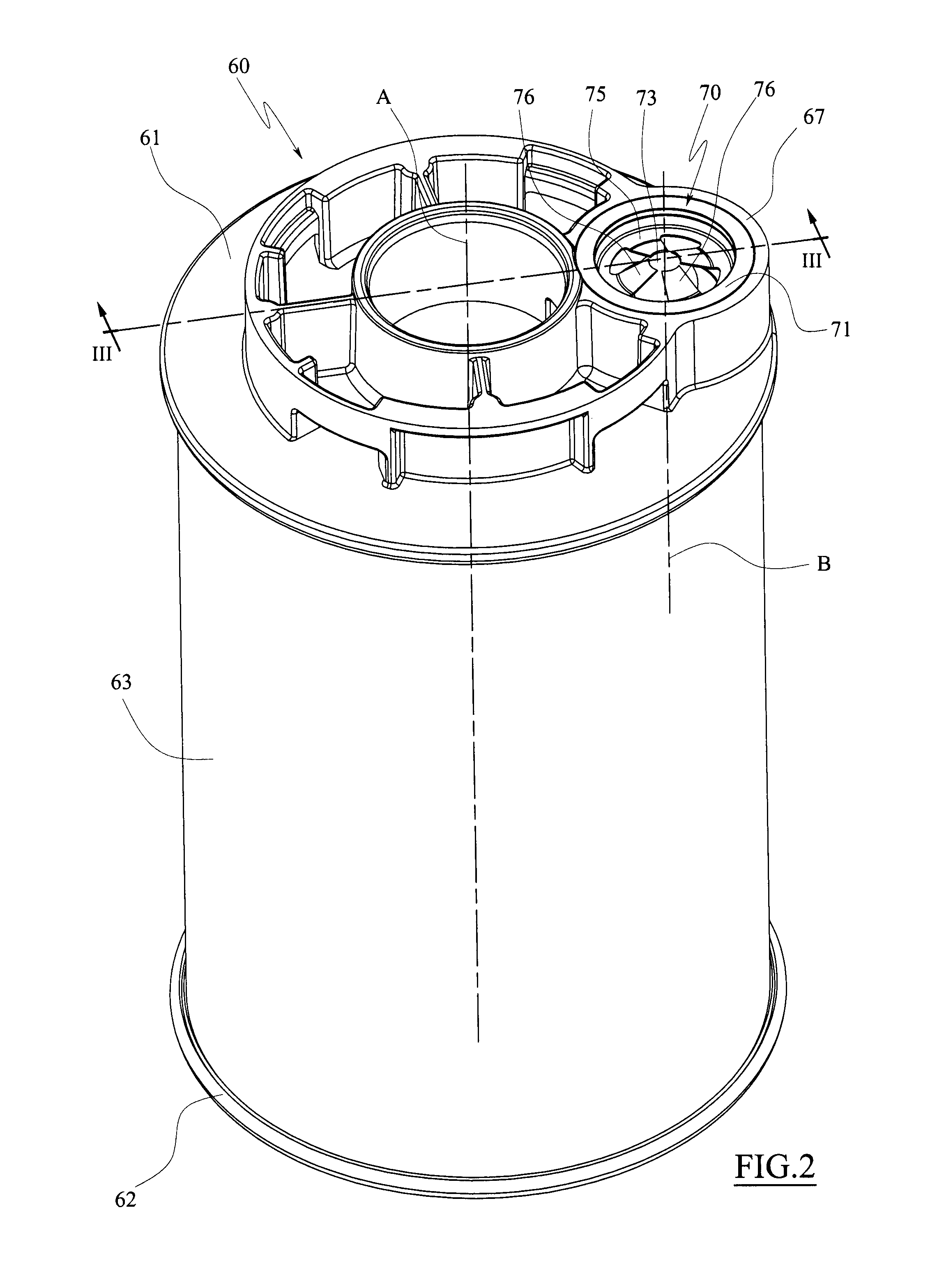
[0073]A sleeve 40 is insert...


PUM

PropertyMeasurementUnit
temperatureaaaaaaaaaa
volumeaaaaaaaaaa

Abstract

A filter cartridge (60, 160) comprising a filter wall (63, 163) having a tubular shape and at least a support plate (61, 161) fixed to an end of the filter wall (63, 163), characterized in that a by-pass conduit (66, 166) is fashioned in the support plate (61, 161), which by-pass conduit (66, 166) is designed to place an internal volume (64, 164) delimited by the filter wall (63, 163) in communication with outside, which by-pass conduit (66, 166) is intercepted by a valve (70, 170) which is associated to the support plate (61, 161) in an out-of-center position with respect to a longitudinal axis (A, A2) of the filter wall (63, 163), the valve (70, 170) comprising an internally-hollow valve body (71, 171), which is provided with a hole (72, 172) suitable for setting the bypass conduit (66, 166) in communication with the internal cavity of the valve body (71, 171), an obturator (73, 174) housed in the internal cavity of the valve body (71, 171), and an elastically-acting element (75, 180) suitable for pressing the obturator (73, 174) against a valve seating (74, 179) such as to close the hole (72, 172), the valve (70, 170) being housed internally of a seating (67, 167) afforded in the support plate (61, 161).

Description

TECHNICAL FIELD[0001]The present invention relates to a filter cartridge and, in particular, to a filter cartridge for filtering fuel or lubricating oil for motoring applications, for example motor cars, lorries, commercial vehicles and work machines, or hydraulic applications.BACKGROUND ART[0002]As is known, the filtration of fuel or lubricating oil is generally obtained with a filter comprising an external casing provided with an inlet for fluid to be filtered and a outlet for the filtered fluid, and a filter cartridge destined to sub-divide the internal volume of the casing into two distinct chambers, of which a first chamber communicates with the inlet and a second chamber communicates with the outlet.[0003]In this way, the fluid which flows from the inlet towards the outlet of the filter is forced to cross the filter wall which retains the impurities that may be present therein.[0004]A typical filter cartridge comprises a tubular filter wall, for example a pleated filter wall o...

Claims


Application Information

Patent Timeline
Patent Type & Authority Patents(United States)
IPC IPC(8): B01D27/10
CPCB01D35/147B01D2201/291B01D35/1475
Inventor GIRONDI, GIORGIO
Owner UFI FILTERS SPA
Why Eureka
Try Eureka