Filter group

a filter group and filter cartridge technology, applied in the field of filter cartridges, can solve the problems of inability to reliably and not, increase the production the casing (support flange), and the maintenance operation cost of the filter cartridge over time, and achieve the effect of simple, rational and relatively inexpensiv

Active Publication Date: 2016-04-19
UFI FILTERS SPA
View PDF21 Cites 5 Cited by
  • Summary
  • Abstract
  • Description
  • Claims
  • Application Information

AI Technical Summary

Benefits of technology

[0017]An aim of the present invention is to obviate the above-mentioned drawbacks of the prior art, with a solution that is simple, rational and relatively inexpensive.
[0021]Thanks to this solution, the disengaging operations of the filter cartridge are facilitated, and it is possible to use hooking elements which are sufficiently rigid and resistant and suited to supporting filter cartridges of considerable weight.
[0022]Further, thanks to this solution the filter group is reliable in use, is relatively inexpensive and simple to realise with respect to bayonet-coupling systems commonly used in the sector.
[0025]Thanks to this solution, the installation of the filter cartridge is decidedly simple and rapid.
[0030]Thanks to this solution, the filter cartridge is always guided towards the engaging seating and therefore the alignment of the engaging elements with the seating itself is facilitated; in this way the engagement can be achieved by means of a contained translation of the filter cartridge towards the body destined to support it.
[0034]In this way, the disengaging operations of the filter cartridge from the body destined to support the filter cartridge are even easier, more rapid and more reliable.

Problems solved by technology

Because of the significant dimensions of the filter cartridge, the installation and replacement thereof in these applications can represent a problem connected to the step of moving and manoeuvring it.
These bayonet couplings, however, exhibit some drawbacks due mainly to the required complexity of the engagement.
These blocking systems are on the one hand not particularly reliable and not very resistant over time, especially after repeated replacements of the filter cartridge, and on the other hand they lead to an increase in production costs of the filter cartridge and the casing (support flange) as well as costs over time for maintenance operations for replacing the filter cartridge.
A second known type of engagement, alternative to the above-described bayonet couplings, comprises axial snap-engagements, which are however not used in air filter groups, where there are high flow rates of air to be filtered, as the weight and large dimensions of the filter cartridges would made the exact positioning of the engaging means difficult to assess.
Further, the need to ensure engaging of a filter cartridge of considerable weight would necessarily lead to realising an axial snap-fit that would be hard to remove.

Method used


Image

  • Filter group
  • Filter group
  • Filter group

Examples


Embodiment Construction

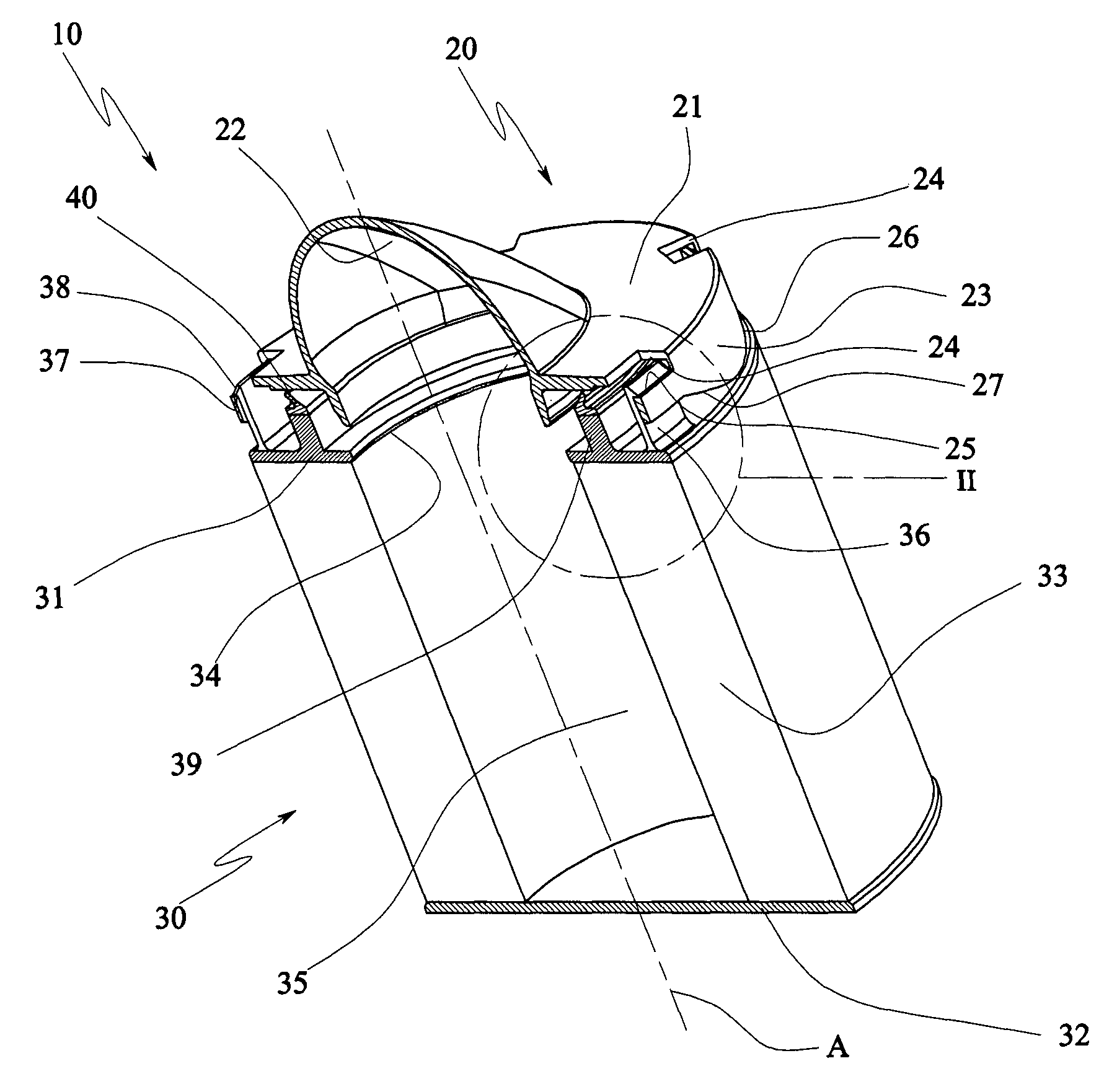
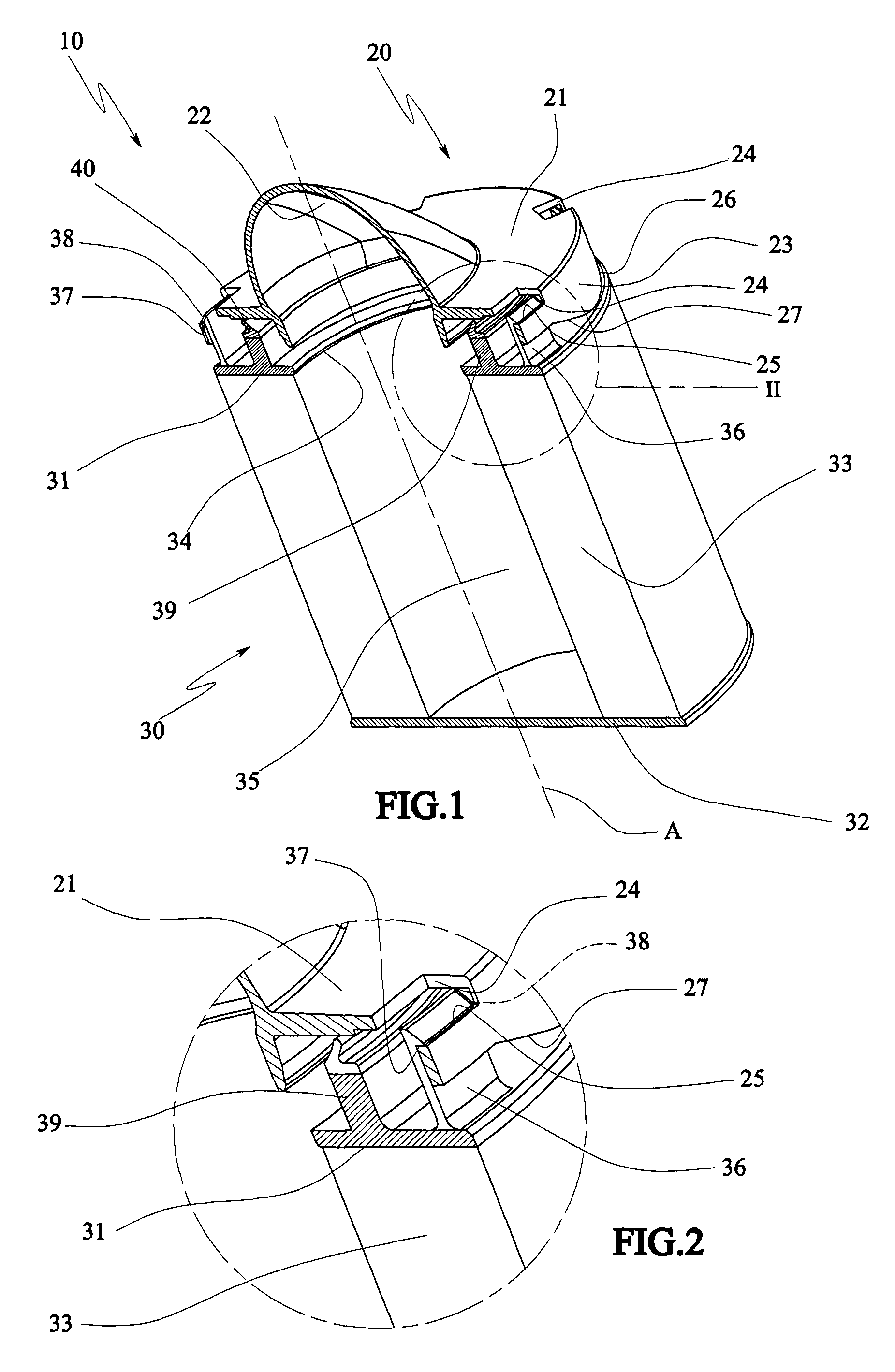
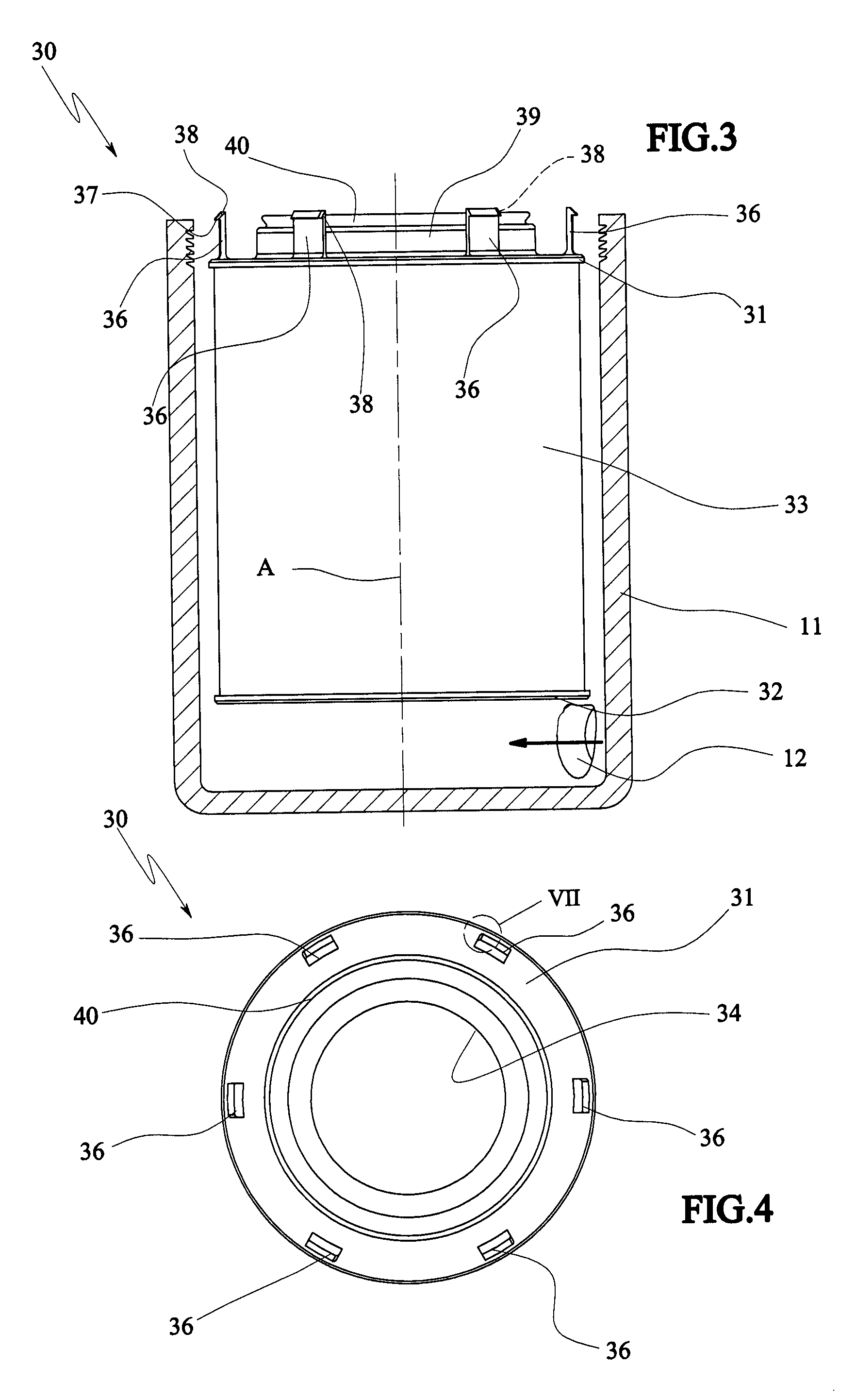
[0051]The filter group 10 illustrated in FIG. 1 is an air filter destined to be applied in the motor vehicle sector, in particular for motors of heavy duty vehicles such as lorries, buses, commercial vehicles or self-propelling work vehicles. The filter group 10 comprises an external casing, comprising a beaker-shaped body 11 (visible in FIG. 3) and a plate-shaped support body, denoted in its entirety by 20 in the figures, which is suitable for sealedly closing the beaker body 11 (for example by means of threaded organs or the like, directly or indirectly by means of a cover) and for supporting a filter cartridge 30 suitable for being arranged internally of the beaker body.

[0052]The beaker body 11 further defines an inlet hole 12 for the air to be filtered.

[0053]The support plate 20 is defined by an annular flange 21 provided with an outlet conduit 22, defining the outlet passage hole of the filtered air, which for example is located superiorly to the annular flange.

[0054]On the opp...


PUM

PropertyMeasurementUnit
volumeaaaaaaaaaa
thicknessaaaaaaaaaa
internal volumeaaaaaaaaaa

Abstract

A filter cartridge (30) comprising a filter membrane (33) and at least a support element (31) fixed to the filter membrane (33), the support element being provided with at least a snap-engaging element (36) suitable for snap-engaging to a support body (20) following a reciprocal translation between the filter cartridge (30) and the support body (20) along a nearing axis (A), the support element (31) further comprising disengaging means (38) suitable for disengaging the snap-engaging element (36) from the support body (20) following a reciprocal rotation between the filter cartridge (30) and the support body about the axis (A).

Description

TECHNICAL FIELD[0001]The present invention relates to a filter cartridge and a relative filter group. The invention mainly relates to a filter group for comburent air which is conveyed internally of internal combustion engines; however the filter might be used for filtration of other fluids, such as for example exhaust gases, oils or fuel.[0002]In greater detail, the invention relates to air filter groups, especially in applications in which a high flow of air to be filtered is required, such as for example—in motoring applications—lorries, buses, commercial vehicles and work machines, or in industrial applications.BACKGROUND ART[0003]As is known, the filtering of air in the motoring or industrial field is generally obtained by means of a filter group which comprises an external casing provided with an inlet for fluid to be filtered and an outlet of filtered fluid, and a filtering cartridge suitable for defining a chamber, for example external, communicating with the inlet of the fl...

Claims


Application Information

Patent Timeline
Patent Type & Authority Patents(United States)
IPC IPC(8): B01D46/00B01D46/24B01D29/15
CPCB01D29/15B01D46/2414B01D46/001B01D2201/291B01D2201/305B01D2201/4007B01D2201/4084B01D2265/028B01D27/08B01D35/30B01D63/06B01D46/2411B01D46/543
Inventor GIRONDI, GIORGIO
Owner UFI FILTERS SPA
Why Eureka
Try Eureka