Close-wound coil and medical treatment tool using this coil

a technology of close-wound coils and medical treatment tools, which is applied in the direction of surgical forceps, endoscopic cutting instruments, mechanical equipment, etc., can solve the problems of conventional close-wound coils, and achieve good rotation transmission performan

Active Publication Date: 2014-03-18
OLYMPUS CORP
View PDF17 Cites 2 Cited by
  • Summary
  • Abstract
  • Description
  • Claims
  • Application Information

AI Technical Summary

Benefits of technology

[0011]The present invention has been made in order to solve the above problems. Accordingly, it is an object of the present invention to provide a close-wound coil having a good rotation transmission performance, and a medical treatment tool using the close-wound coil.
[0012]According to an aspect of the present invention, there is provided a close-wound coil comprising a first predetermined axis, and a wire which is wound spirally and closely over a predetermined length around the first axis, and has a center axis extending in the length direction thereof. The wire has a section vertical to the center axis, a second axis passing across the center axis within the section and vertical to the first axis, and a third axis passing across the center axis within the section and vertical to the second axis. The wire has substantially the same flexural rigidity as that of a reference wire having a perfect circle section with a diameter of the longer one of section along the second axis and section along third axis and the torsional rigidity of the wire is lower than the torsional rigidity of the reference wire.
[0018]As explained above, according to the present invention, there is provided a close-wound coil having a good rotation transmission performance, and a medical treatment tool using the close-wound coil.

Problems solved by technology

There is one serious problem in a conventional close-wound coil.

Method used


Image

  • Close-wound coil and medical treatment tool using this coil
  • Close-wound coil and medical treatment tool using this coil
  • Close-wound coil and medical treatment tool using this coil

Examples


first embodiment

[0095]FIG. 5 to FIG. 7 show the present invention.

[0096]As shown in FIG. 5, a close-wound coil 20 is formed by winding a wire 18 with a non-circular section spirally and closely over a predetermined length around a predetermined first axis O1. The wire 18 is formed so that in a section S vertical to a center axis O2 extending in the lengthwise direction of the wire, the second moment of area I1 concerning a second axis O3 passing across a center axis O2 and vertical to the first axis O1 is smaller than the second moment of area I2 concerning a third axis O4 passing across the center axis O2 of the section S and vertical to the second axis O3. Concretely, the section S of the wire 18 is substantially rectangular where the dimension Y along the second axis O3 is larger than the dimension X along the third axis O4 (the vertical-to-horizontal ratio of the section S is larger than 1, and has an arc with a large curvature at both ends along the second axis O3). In other words, the close-w...

third embodiment

[0151]FIG. 20 to FIG. 22B show the present invention.

[0152]As shown in these drawings, the close-wound coil 20B of this embodiment is formed by a wire 18B with the elliptical section. The other characteristics and shapes are the same as the first embodiment. Therefore, the same functions and effects as those of the first embodiment can be obtained.

[0153]FIG. 23 to FIG. 25 show a fourth embodiment.

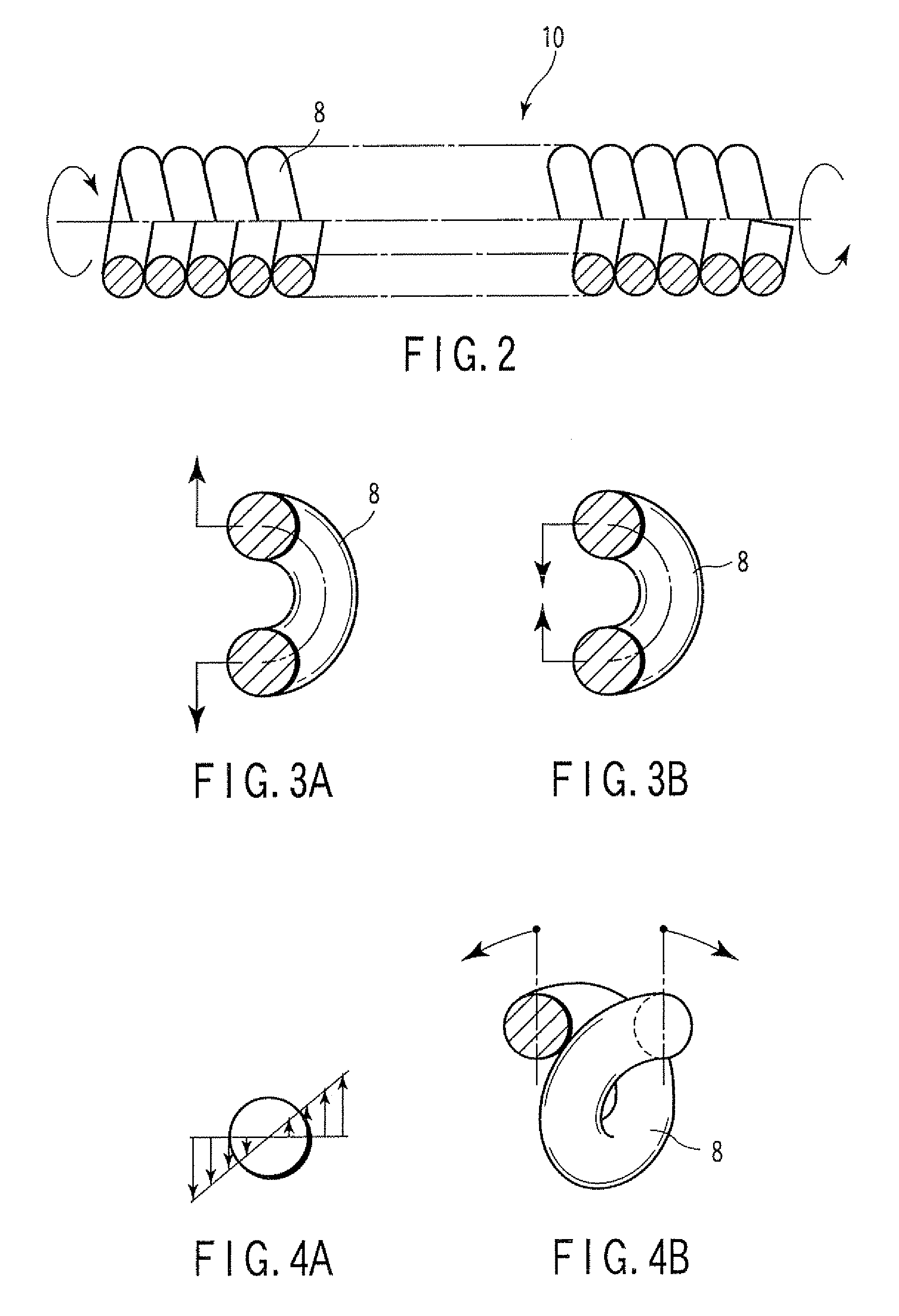
[0154]As shown in these drawings, a close-wound coil 20C of this embodiment is formed by winding a set of wires 18C formed by overlapping two circular-section wires 8 in the radial direction, spirally and closely over a predetermined length around a predetermined first axis O1. The set of wires 18C formed by overlapping two circular-section wires 8 in the radial direction (refer to FIG. 24) can make a section S′ with a vertical-to-horizontal ratio larger than 1 similar to the section S of the wire 18 of the first embodiment. Therefore, the close-wound coil 20C formed by winding closely the ...

fifth embodiment

[0156]FIG. 28 to FIG. 30 show the present invention.

[0157]As show in these drawings, a close-wound coil 20D of this embodiment is formed by winding a wire 28 with a circular section (the vertical-to-horizontal ratio of the section is 1:1) spirally and closely over a predetermined length around a predetermined first axis O1. The wire 28 is not homogeneous in the inside, and the both side areas R1 and R1 (the areas with the crescent section) have low rigidity, and the area R2 (the area with a substantially rectangular section) near the center axis O2 held by these areas R1 and R1 has high rigidity.

[0158]Therefore, the wire 28 of this embodiment has the equivalent flexural rigidity and lower torsional rigidity, compared with a circular-section homogeneous material wire with the same dimension. Thus, the close-wound coil 20D of this embodiment is increased in the torsional rigidity and decreased in the flexural rigidity, compared with the close-wound coil formed by the homogeneous mater...


PUM


Abstract

A medical treatment tool is provided having: a force transmission member having a distal end and a proximal end; an end effector which is provided on the distal end of the force transmission member in a non-rotatable manner with respect to the force transmission member; a control wire which is inserted into the force transmission member; and a rotatable coupling which is provided between the end effector and the control wire, and is coupled rotatably to the end effector with respect to the control wire.

Description

CROSS-REFERENCE TO RELATED APPLICATIONS[0001]This application is a continuation application of U.S. patent application Ser. No. 10 / 790,261 filed Mar. 1, 2004, now abandoned, which is based upon and claims the benefit of priority from prior Japanese Patent Application No. 2003-056215, filed Mar. 3, 2003, the entire contents of each of which are incorporated herein by reference.BACKGROUND OF THE INVENTION[0002]1. Field of the Invention[0003]The present invention relates to a close-wound coil formed by winding a wire spirally and closely over a predetermined length, and a medical treatment tool using the close-wound coil.[0004]2. Description of the Related Art[0005]Generally, a medical treatment tool inserted into a human body through an endoscope channel comprises a treatment section provided at a distal end, a control section provided at a proximal end, and a transmission member to transmit the operating force from the control section to the treatment section.[0006]The transmission m...

Claims


Application Information

Patent Timeline
Patent Type & Authority Patents(United States)
IPC IPC(8): A61B17/10A61B1/00A61B18/14A61B17/28A61B17/12A61B17/128A61B17/32F16C1/02A61B17/00
CPCA61B17/00234A61B18/1492A61B2018/1407A61B17/1285A61B17/10A61B17/320016A61B17/32056F16C1/02A61B2017/2905F16C2316/10
Inventor SUZUKI, TAKAYUKI
Owner OLYMPUS CORP
Why Eureka
Try Eureka