Supercharge Your Innovation With Domain-Expert AI Agents!

Wind farm, wind power plant in a wind farm and operating control for this purpose

a technology of wind farm and wind power plant, which is applied in the direction of engine control, motors, wind energy generation, etc., can solve the problems of affecting the operation of radar systems, corresponding parts of the rotor structure, and the inability to easily distinguish the image of flying targets from the real flying targets, so as to reduce the interference of radar systems

Active Publication Date: 2014-04-29
AIRBUS DEFENCE & SPACE
View PDF16 Cites 4 Cited by
  • Summary
  • Abstract
  • Description
  • Claims
  • Application Information

AI Technical Summary

Benefits of technology

Significantly reduces the frequency of interfering radar reflections, enhancing radar system accuracy and flight safety by minimizing the probability of rotor blades being misinterpreted as flying objects, while maintaining efficient energy conversion and reducing synchronization effort.

Problems solved by technology

Wind power plants of this type can cause disturbances in the operation of radar systems.
In the case of radar systems with moving target recognition, which evaluate double displacements of this type, this can lead undesirably to corresponding parts of the rotor structure, that is, e.g., rotor blades, being misinterpreted as “flying objects.” Because the rotor structure parts moving towards the radar system or away from the radar system cause double displacements in the reflected radar radiation, a target imaging may be produced on the radar screen that cannot be easily distinguished from a real flying target.
This problem is further intensified in that wind power plants are often installed in a spatial distribution of a plurality of such wind power plants (so-called “wind farm”).
The particularly interfering radar reflections on rotating rotor structural parts, such as rotor blades, take place primarily when these structural parts extend orthogonally to the direction of incidence of the radar radiation.
For example, for a wind power plant with a rotor structure pivoted about a horizontal axis and having rotor blades projecting radially therefrom, particularly interfering radar reflections result when a rotor blade is pointing vertically upwards or downwards.
A high interference of the radar operation by the wind farm results when a rotor blade of at least one of the wind power plants is perpendicular during the chronological radar illumination intervals.
However, the disadvantage with this approach is the associated reduction of the design freedom regarding the structure and material of the rotor blade.
Apart from a restriction of the design freedom for the wind farm (or for the radar system) associated therewith, the reduction of interference in the radar operation that can be achieved thereby is often unsatisfactory.

Method used


Image

  • Wind farm, wind power plant in a wind farm and operating control for this purpose
  • Wind farm, wind power plant in a wind farm and operating control for this purpose
  • Wind farm, wind power plant in a wind farm and operating control for this purpose

Examples


Embodiment Construction

[0069]The particulars shown herein are by way of example and for purposes of illustrative discussion of the embodiments of the present invention only and are presented in the cause of providing what is believed to be the most useful and readily understood description of the principles and conceptual aspects of the present invention. In this regard, no attempt is made to show structural details of the present invention in more detail than is necessary for the fundamental understanding of the present invention, the description taken with the drawings making apparent to those skilled in the art how the several forms of the present invention may be embodied in practice.

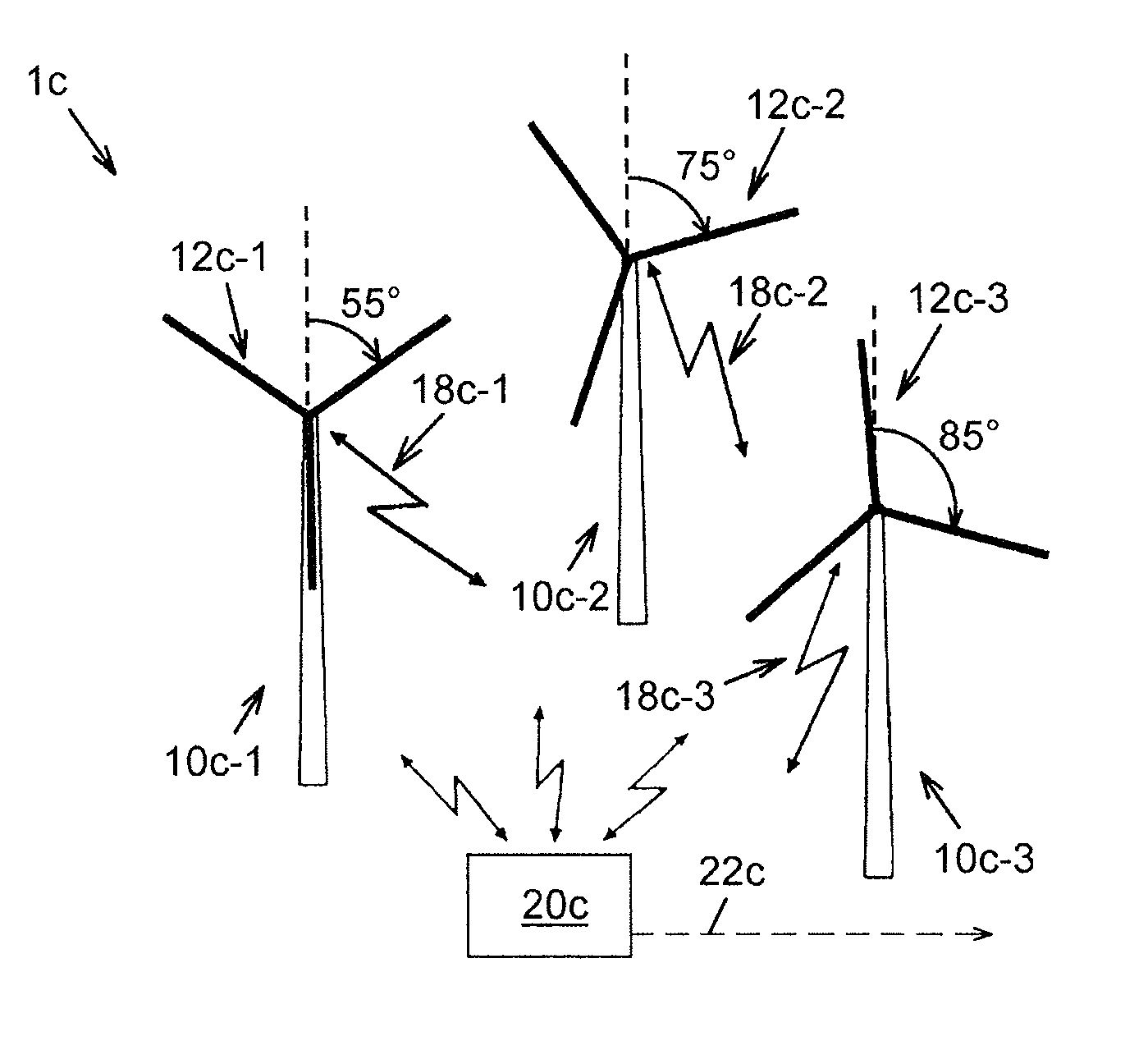
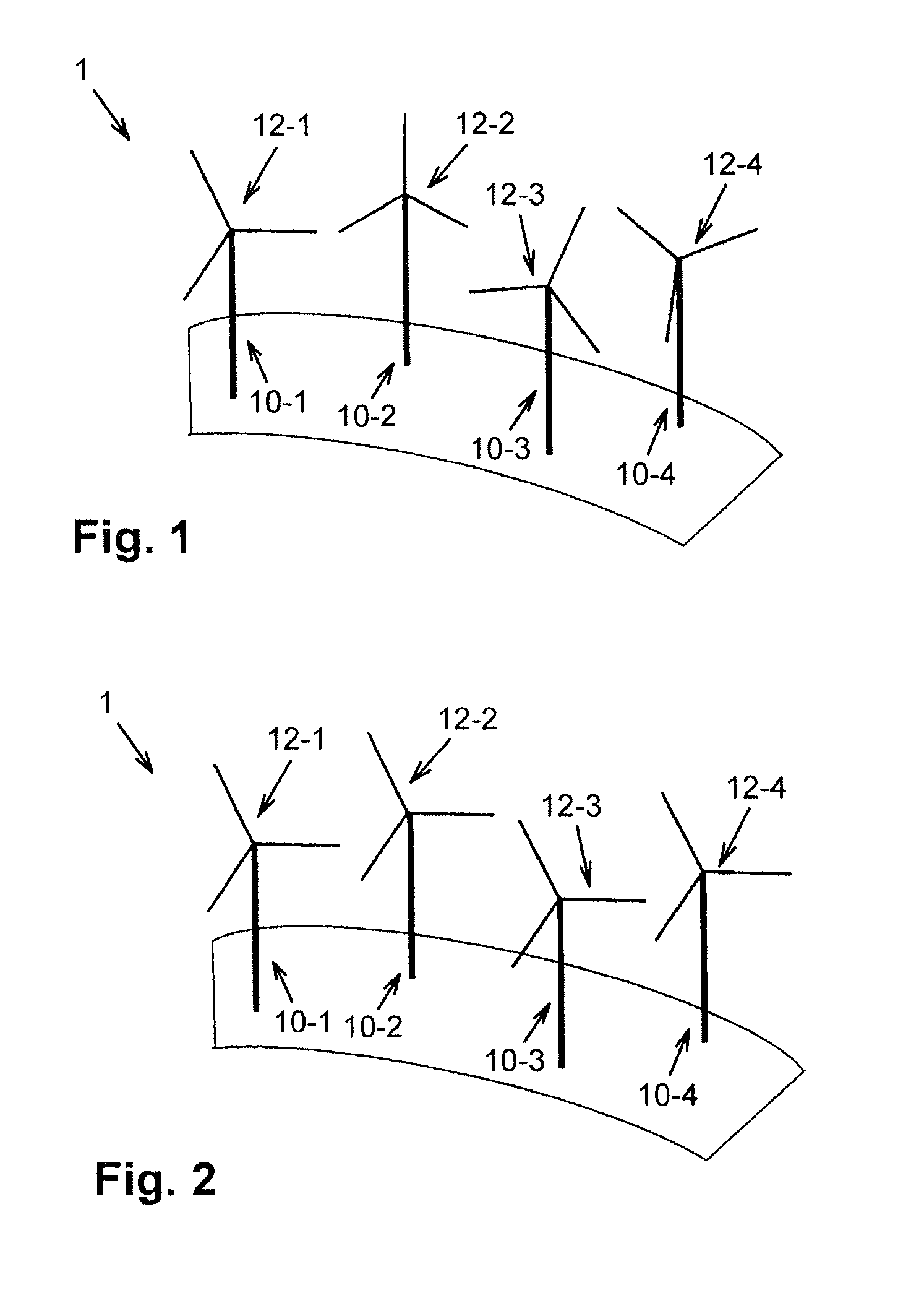
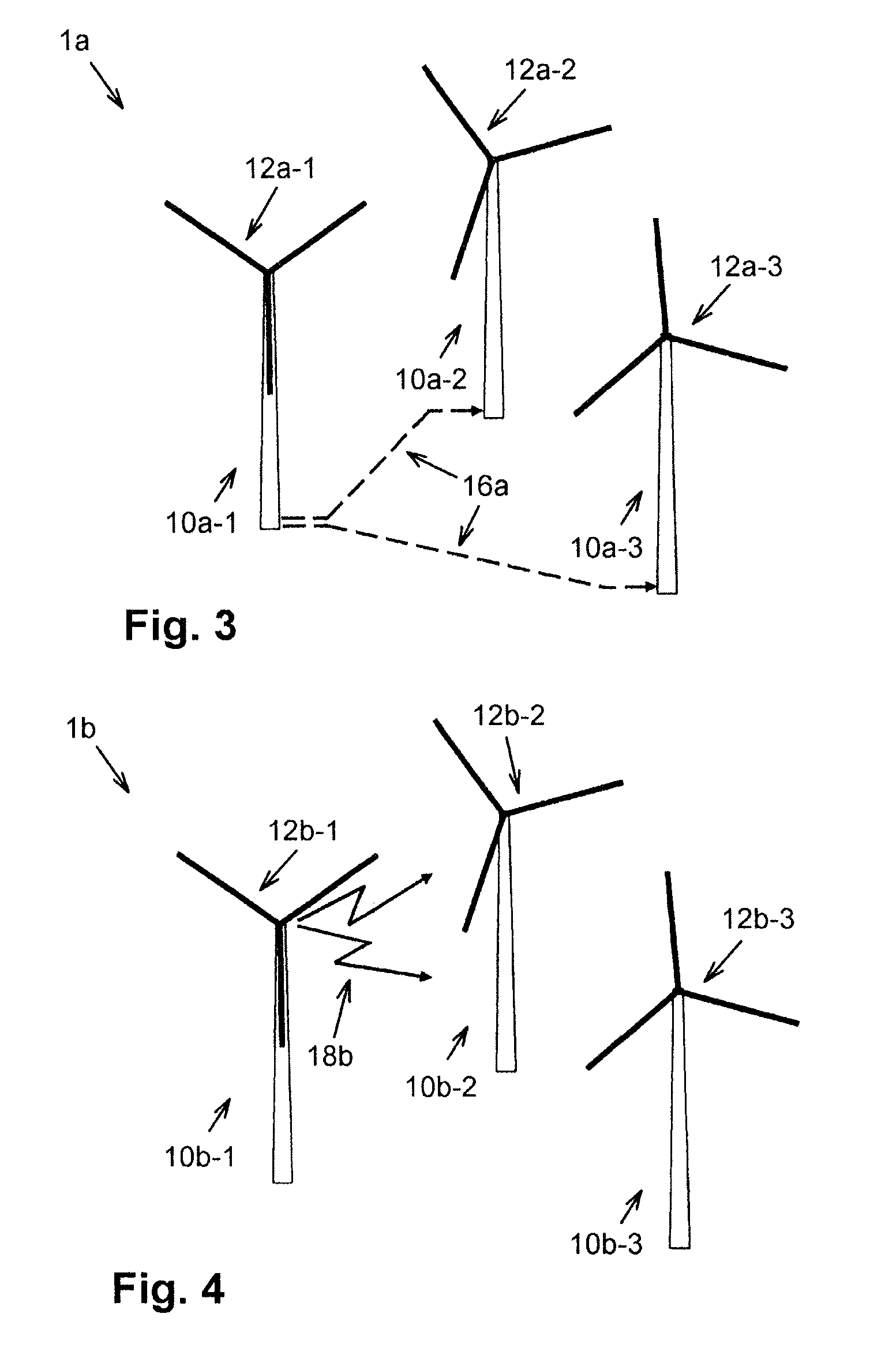
[0070]FIG. 1 shows a wind farm 1 comprising four wind power plants 10-1 through 10-4 and control device (not shown) for controlling the operation of the individual wind power plants 10-1 through 10-4.

[0071]The reference numbers of components provided several times in one embodiment, but analogous in their action, such as,...


PUM


Abstract

Wind farm and method of controlling operation of a wind farm. The wind farm including a plurality of wind power plants, each equipped in a same manner with a pivoted rotor structure and a control device for controlling the operation of the individual wind power plants. The control device is structured and arranged to synchronize the rotary motions of the rotor structures of at least some of the plurality of wind power plants.

Description

CROSS-REFERENCE TO RELATED APPLICATIONS[0001]The present application claims priority under 35 U.S.C. §119 of German Patent Application No. 10 2010 050 591.9, filed on Nov. 5, 2010, the disclosure of which is expressly incorporated by reference herein in its entirety.BACKGROUND OF THE INVENTION[0002]1. Field of the Invention[0003]Embodiments of the present invention relates to energy generation from wind power using wind power plants assembled spatially to form a “wind farm.” In particular, embodiments relates to a wind farm, a method for operating control of wind power plants, a wind power plant, and a method for operating control of a wind power plant.[0004]2. Discussion of Background Information[0005]Wind power plants of the type of interest here comprise a pivoted rotor structure, which is typically formed by a pivoted rotor shaft, a rotor hub at one end of the rotor shaft, and one or more rotor blades (rotor vanes) projecting from the rotor hub in the radial direction.[0006]The ...

Claims


Application Information

Patent Timeline
Patent Type & Authority Patents(United States)
IPC IPC(8): F03D9/00
CPCY02E10/723F03D7/048F03D7/022F03D7/0204F05B2270/327F05B2270/805F05B2270/326Y02E10/72F03D7/0276F05B2240/221
Inventor BETTERMANN, JOACHIMBLOCH, BORISFRYE, ANDREASGOTTSCHALK, MICHAEL
Owner AIRBUS DEFENCE & SPACE
Features
  • R&D
  • Intellectual Property
  • Life Sciences
  • Materials
  • Tech Scout
  • Unparalleled Data Quality
  • Higher Quality Content
  • 60% Fewer Hallucinations
Learn More