Artificial SI joint

a technology of sacroiliac joints and joints, applied in the direction of prosthesis, internal osteosynthesis, osteosynthesis devices, etc., can solve the problem of disrupting the normal function of the si-join

Active Publication Date: 2014-07-15
SI BONE INC
View PDF271 Cites 52 Cited by
  • Summary
  • Abstract
  • Description
  • Claims
  • Application Information

AI Technical Summary

Problems solved by technology

When the joint has excessive motion, normal function of SI-Joint can be disrupted and the joint may become inflamed causing pain.

Method used


Image

  • Artificial SI joint
  • Artificial SI joint
  • Artificial SI joint

Examples


Embodiment Construction

[0042]Reference will now be made in detail to exemplary embodiments of the invention, examples of which are illustrated in the accompanying drawings. While the invention will be described in conjunction with the exemplary embodiments, it will be understood that they are not intended to limit the invention to those embodiments. On the contrary, the invention is intended to cover alternatives, modifications and equivalents, which may be included within the spirit and scope of the invention as described herein.

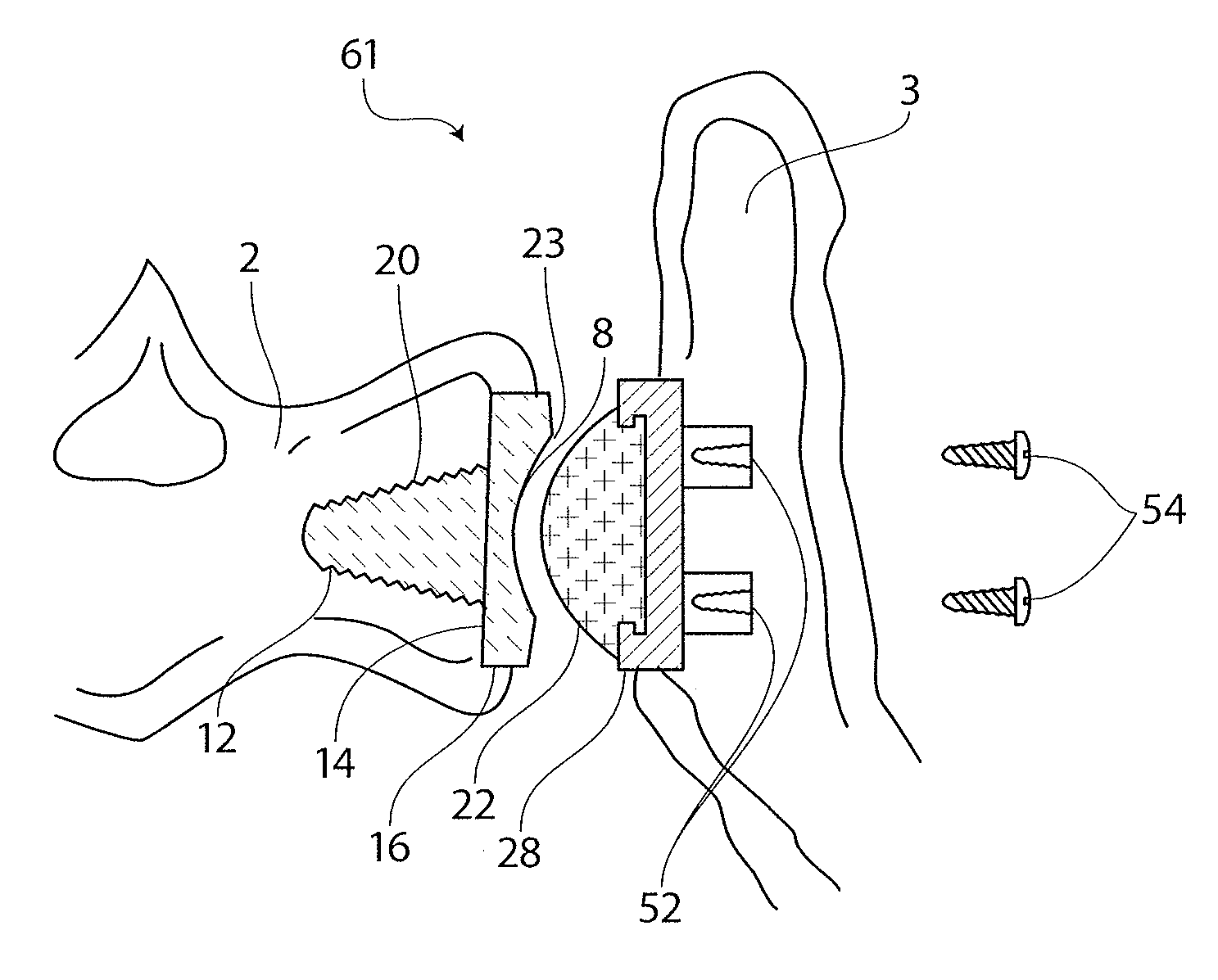
[0043]Various aspects of the present invention relate to an artificial sacroiliac joint prosthesis. In various embodiments, the artificial joint is implanted into the sacroiliac joint (SI-Joint).

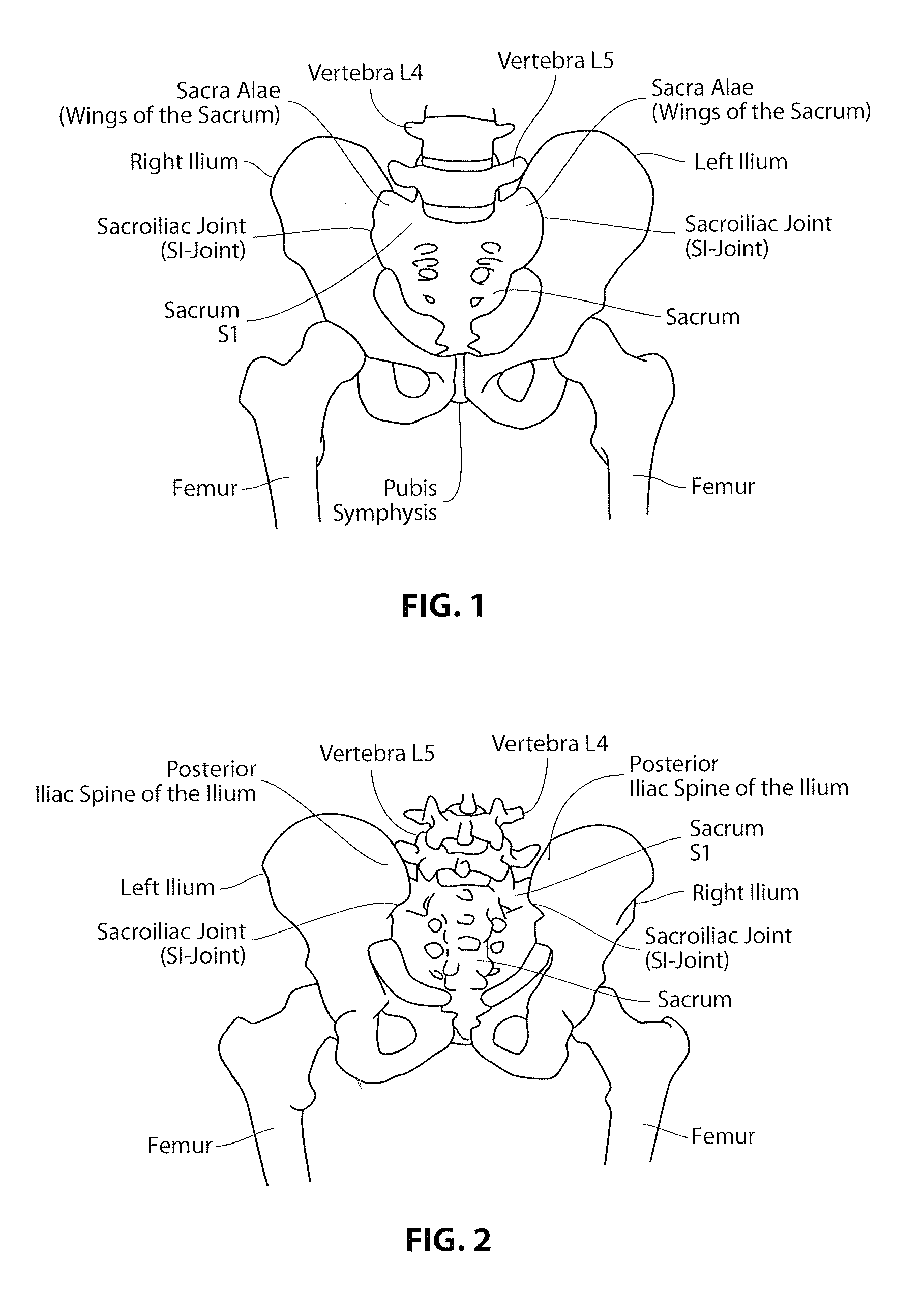
[0044]FIGS. 1-2 are, respectively, anterior and posterior views of the human hip girdle including the sacrum and the hip bones (the right ilium and the left ilium), the sacrum being connected with both hip bones at the SI-Joints.

[0045]Each joint is encased and strengthened by two main lig...


PUM

PropertyMeasurementUnit
lengthaaaaaaaaaa
widthaaaaaaaaaa
heightaaaaaaaaaa

Abstract

An artificial SI-Joint includes a sacrum component and an ilium component. The sacrum component may include a ridge, foundation, perimeter surface and a fitting member. The ilium component may include a polybearing, edge, foundation, perimeter surface, and a ridge or sockets. The fitting member of the sacrum component may engage the polybearing of the ilium component to restore normal movement of the SI-Joint. The artificial SI-Joint may be implanted as a single unit or as separate pieces that are coupled together.

Description

CROSS REFERENCE TO RELATED APPLICATIONS[0001]This patent application claims priority to U.S. Provisional Application No. 61 / 609,195, titled “ARTIFICIAL SI JOINT”, filed on Mar. 9, 2012, which is herein incorporated by reference in its entirety.INCORPORATION BY REFERENCE[0002]All publications and patent applications mentioned in this specification are herein incorporated by reference to the same extent as if each individual publication or patent application was specifically and individually indicated to be incorporated by reference.FIELD[0003]The present invention generally relates to an artificial sacroiliac joint prosthesis. In various respects, the invention is directed to a sacroiliac joint prosthesis for movably connecting the sacrum to the ilium.BACKGROUND[0004]The human hip girdle (see FIGS. 1 and 2) is made up of three large bones joined by two relatively immobile joints. One of the bones is called the sacrum and it lies at the bottom of the lumbar spine, where it connects wi...

Claims


Application Information

Patent Timeline
Patent Type & Authority Patents(United States)
IPC IPC(8): A61F2/30
CPCA61F2002/3038A61B17/86A61F2002/30879A61F2/30988A61F2310/00976A61F2002/30133A61F2310/0097A61F2002/30995A61F2/44A61F2002/30331
Inventor MAULDIN, RICHARD, G.
Owner SI BONE INC
Why Eureka
Try Eureka