Adjustable dumbbell

a dumbbell and adjustable technology, applied in the field of adjustable exercise devices or dumbbells, can solve the problems of taking a long time to thread and unthread the lock nuts from the handle, and achieve the effects of improving structure, easy and quick adjustment of weight members, and convenient and quick adjustmen

Inactive Publication Date: 2014-07-29
BETO ENG & MARKETING
View PDF15 Cites 5 Cited by
  • Summary
  • Abstract
  • Description
  • Claims
  • Application Information

AI Technical Summary

Benefits of technology

[0010]The primary objective of the present invention is to provide an adjustable exercise device or dumbbell including an improved structure for allowing the weight members to be easily and quickly and readily and adjustably attached to or disengaged from the weight carrier or handle and for allowing the adjustable dumbbell to be easily operated by the users.
[0011]The other objective of the present invention is to provide an adjustable exercise device or dumbbell including an improved structure for allowing the weight members to be easily and quickly and readily and adjustably attached to or disengaged from the weight carrier or handle without supporting the weight members in a supporting base.
[0012]In accordance with one aspect of the invention, there is provided an adjustable exercise device comprising a handle including a first end member and a second end member, a first carrier attached to the first end member of the handle, and including a first latch groove formed therein and located around a center portion of the first carrier, and including a cavity formed therein, the first latch groove of the first carrier including a first end portion and a second end portion, a first weight member including a first latch member extended therefrom for engaging with the first latch groove of the first carrier and for detachably attaching the first weight member to the first end member of the handle with the first carrier, the first weight member being rotatable relative to the first carrier and the first end member of the handle for causing the first latch member to move from the first end portion to the second end portion of the first latch groove of the first carrier and for detachably and selectively latching the first weight member to the first end member of the handle with the first carrier, and a lock member slidably attached to the first weight member and including a tongue extendible out of the first weight member for selectively engaging with the cavity of the first carrier and for selectively locking the first weight member to the first end member of the handle when the first latch member of the first weight member is moved to and engaged with the second end portion of the first latch groove of the first carrier, and thus for allowing the weight member to be easily and quickly and readily attached or mounted or secured to or removed or disengaged from the handle without supporting the weight members in a supporting base.
[0018]The first weight member includes a non-circular depression formed therein, and the carrying member includes a non-circular cross section for engaging with the non-circular depression of the first weight member and for preventing the carrying member from being rotated relative to the first weight member. The first weight member includes two apertures formed therein and located around the center portion of the carrying member for selectively engaging with the locking member.

Problems solved by technology

However, it takes a long time to thread and unthread the lock nuts from the handle in order to attach or mount the required or selected number of the weight plates or weight members onto or from the ends of the handle.

Method used


Image

  • Adjustable dumbbell
  • Adjustable dumbbell
  • Adjustable dumbbell

Examples


Embodiment Construction

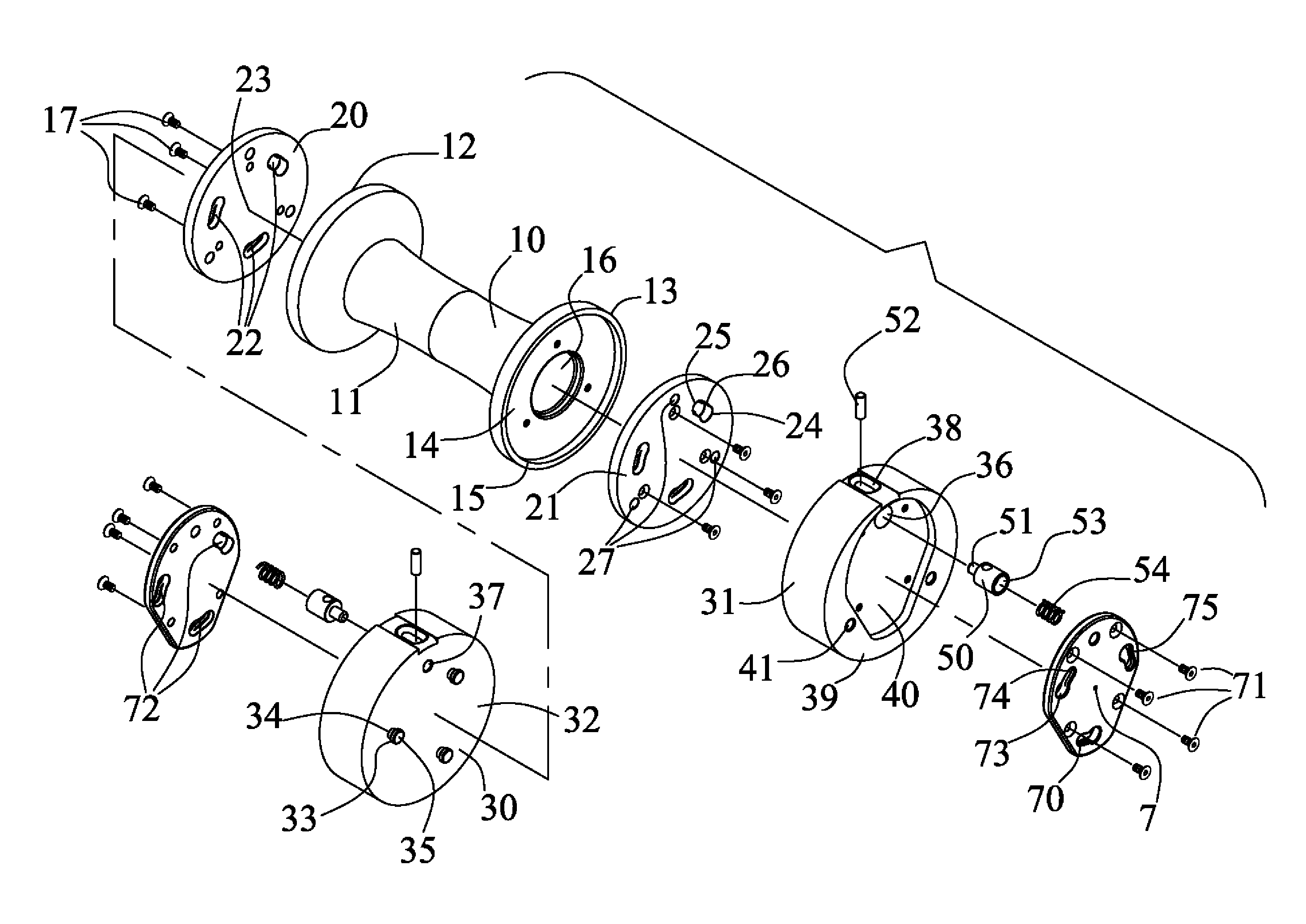
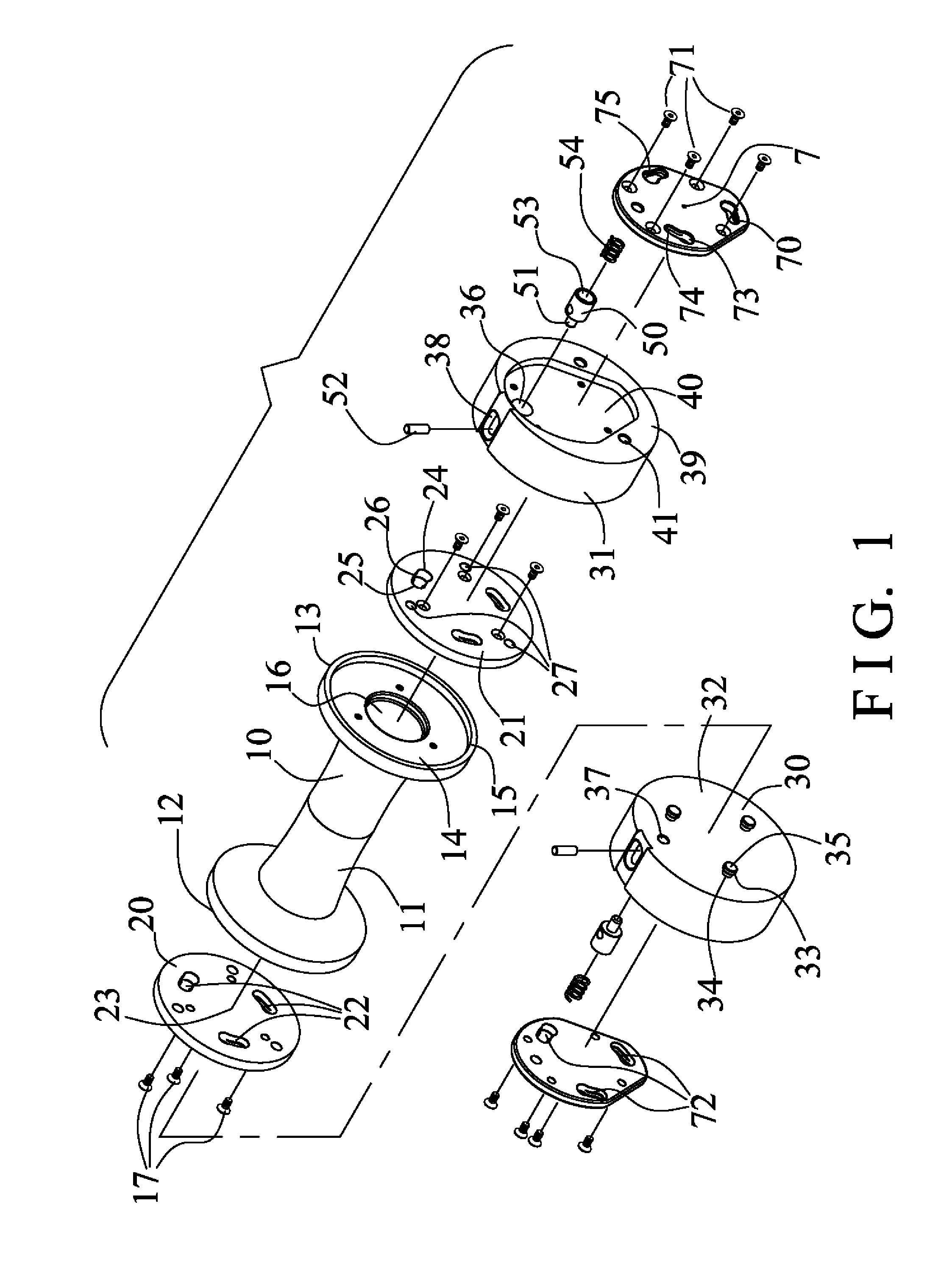
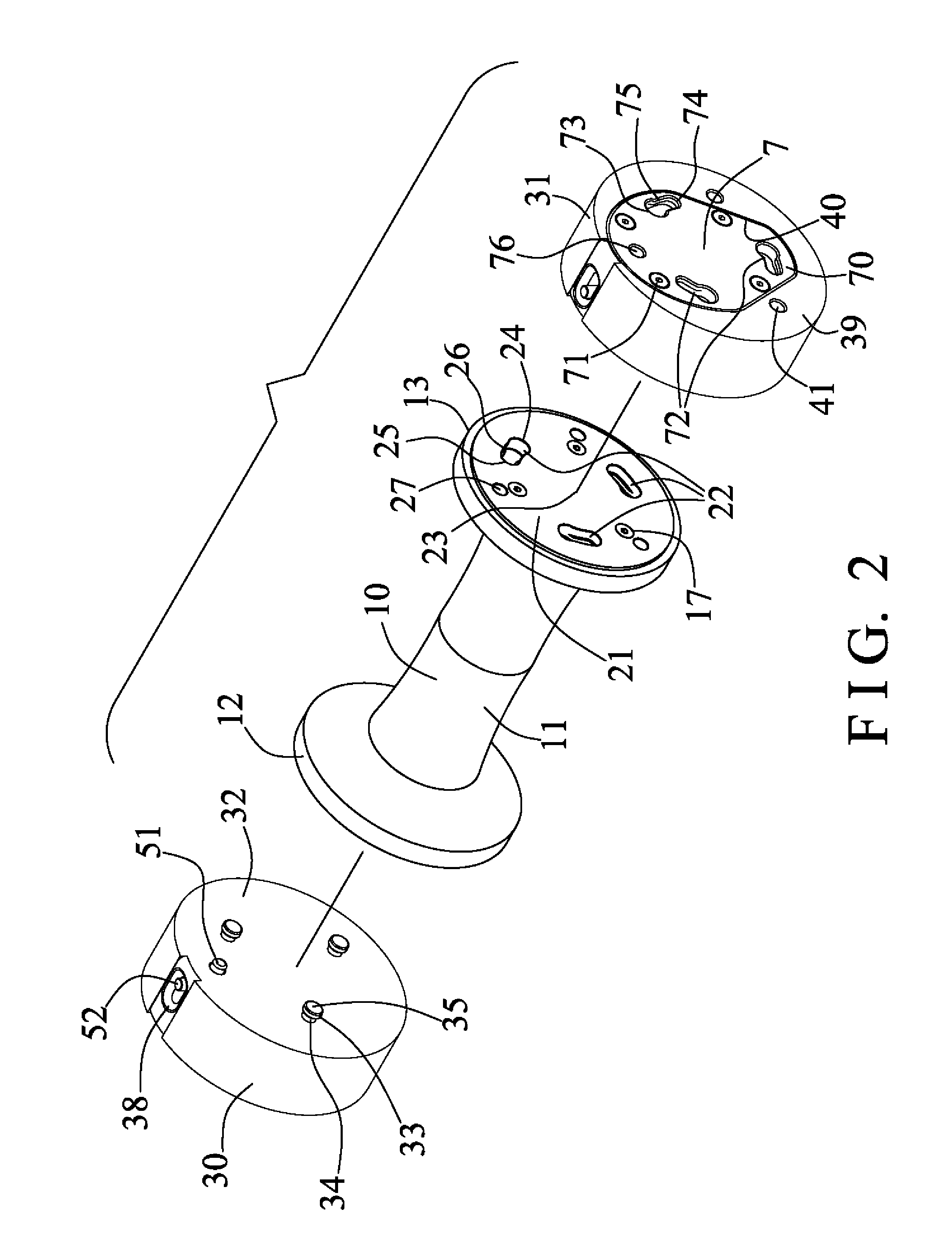
[0037]Referring to the drawings, and initially to FIGS. 1-4, an adjustable dumbbell or barbell or exercise device in accordance with the present invention comprises a longitudinal shaft or handle 10 including a hand grip 11 formed or provided on the middle or center portion thereof for being grasped or held by the user and for carrying or lifting or moving the handle 10 and for allowing the adjustable dumbbell to be easily operated by the user, and including two end plates or end portions or end members 12, 13, such as first and second end members 12, 13 each having a depression or compartment or recess 14 formed therein and opened outwardly and formed or defined by an outer peripheral rib or flange or fence 15, and including a depression or recess or cavity or space 16 formed or provided in the middle or center portion of each of the end portions or end members 12, 13 thereof and communicative with the respective recess 14 of the handle 10. The end members 12, 13 each include an ou...


PUM


Abstract

An adjustable barbell or dumbbell or exercise device includes a handle having two end members, two carriers attached to the end members of the handle respectively, and a weight member having one or more latch members for detachably attaching to the end member of the handle, and a lock member slidably attached to the weight member and having a tongue for engaging with the carrier and for locking the weight member to the handle when the latch members of the weight member are rotated relative to the carrier, the other weight members are attachable to the weight member with the other latch members and the other lock member without supporting the weight members in a supporting base.

Description

BACKGROUND OF THE INVENTION[0001]1. Field of the Invention[0002]The present invention relates to an adjustable exercise device or dumbbell or the like, and more particularly to an adjustable exercise device or dumbbell including an improved structure for allowing the weight members to be easily and quickly and readily and adjustably attached to or disengaged from the weight carrier or handle and for allowing the adjustable dumbbell to be easily operated by the user.[0003]2. Description of the Prior Art[0004]Typical exercise devices or barbells or dumbbells comprise a handle to be grasped or held by the user, and a number of weight plates to be attached onto the ends of the handle for weight lifting or exercising purposes, or for exercising or training the upper muscle groups or the lower muscle groups of the user.[0005]For example, U.S. Pat. No. 5,839,997 to Roth et al., U.S. Pat. No. 6,416,446 to Krull, U.S. Pat. No. 6,656,093 to Chen, U.S. Pat. No. 6,669,606 to Krull, U.S. Pat. No...

Claims


Application Information

Patent Timeline
Patent Type & Authority Patents(United States)
IPC IPC(8): A63B21/00
CPCA63B21/0726A63B21/075
Inventor WANG, LO, PIN
Owner BETO ENG & MARKETING
Why Eureka
Try Eureka