
Portable splint system

a splint system and portable technology, applied in the field of traction splints, can solve the problems of inconvenient patient treatment of many portable splint systems do not allow the flexibility and customization of overhead systems, and the patient is not suitable for treating patients with fused knees. , to achieve the effect of reducing the chance of fracture site collapse, reducing bleeding, and improving patient hygien

Active Publication Date: 2014-10-07
COTTON GERALD
View PDF36 Cites 0 Cited by
  • Summary
  • Abstract
  • Description
  • Claims
  • Application Information

AI Technical Summary

Benefits of technology

[0013]It is a further object of the present invention to provide a portable splint system that can be used to maintain continuous traction on a fracture site.
[0014]It is a further object of the present invention to provide a portable splint system that allows for the treatment of patients with fused knees.
[0015]It is a further object of the present invention to provide a portable splint system that allows for easy access to the patient to improve patient hygiene.
[0016]It is a further object of the present invention to provide a portable splint system that allows for the treatment of multiple fractures simultaneously.
[0017]It is a further object of the present invention to provide a portable splint system that decreases the chances of the fracture site collapse, bleeding, and deep vein thrombosis.
[0022]In addition to the system described above, the present invention also includes a method of transferring a splinted patient from a bed mounted traction apparatus to a portable splint system. First, a limb supporting splint in a bed mounted traction apparatus is secured to a portable base unit. Next, traction force from the bed mounted traction apparatus is transferred to the portable base unit without removal of the traction force. By using this method, continuous traction is maintained, which reduces the chances of a fracture collapse, bleeding and deep vein thrombosis.

Problems solved by technology

However, because of their fixed nature, overhead splint systems do not lend themselves to continently moving the patient from one location to another.
However, because of their relatively compact size, portable splint systems do not allow the flexibility and customization that overhead systems provide.
For example, many portable splint systems are not suitable for treating a patient with a fused knee.
Additionally, portable splint systems are generally not capable of treating multiple fractures simultaneously.
The lack of portability of overhead splint systems and the limited flexibility of portable splint systems often leads to doctors prescribing treatment using an overhead system when the patient is in the hospital bed and a portable splint system when the patient is being transported or treated out of the hospital bed.
This use of dual systems can lead to complications in the treatment of splinted limbs.
This causes complications of its own.
This digging into the mattress causes the ring to flatten out.
Prolonged contact between the ring and patient in this manner can cause the patient's skin to break down, particularly under the gluteal fold.
Furthermore, patient hygiene can become problematic with current splint systems.
Accordingly, the frequency of bed linen changes is often reduced and as a result patient hygiene suffers.

Method used


Image

  • Portable splint system
  • Portable splint system
  • Portable splint system

Examples


Embodiment Construction

[0032]While this invention is susceptible of embodiments in many different forms, there are shown in the drawings and will herein be described in detail, preferred embodiments of the invention with the understanding that the present disclosure is to be considered as an exemplification of the principles of the invention and is not intended to limit the broad aspect of the invention to the embodiments illustrated.

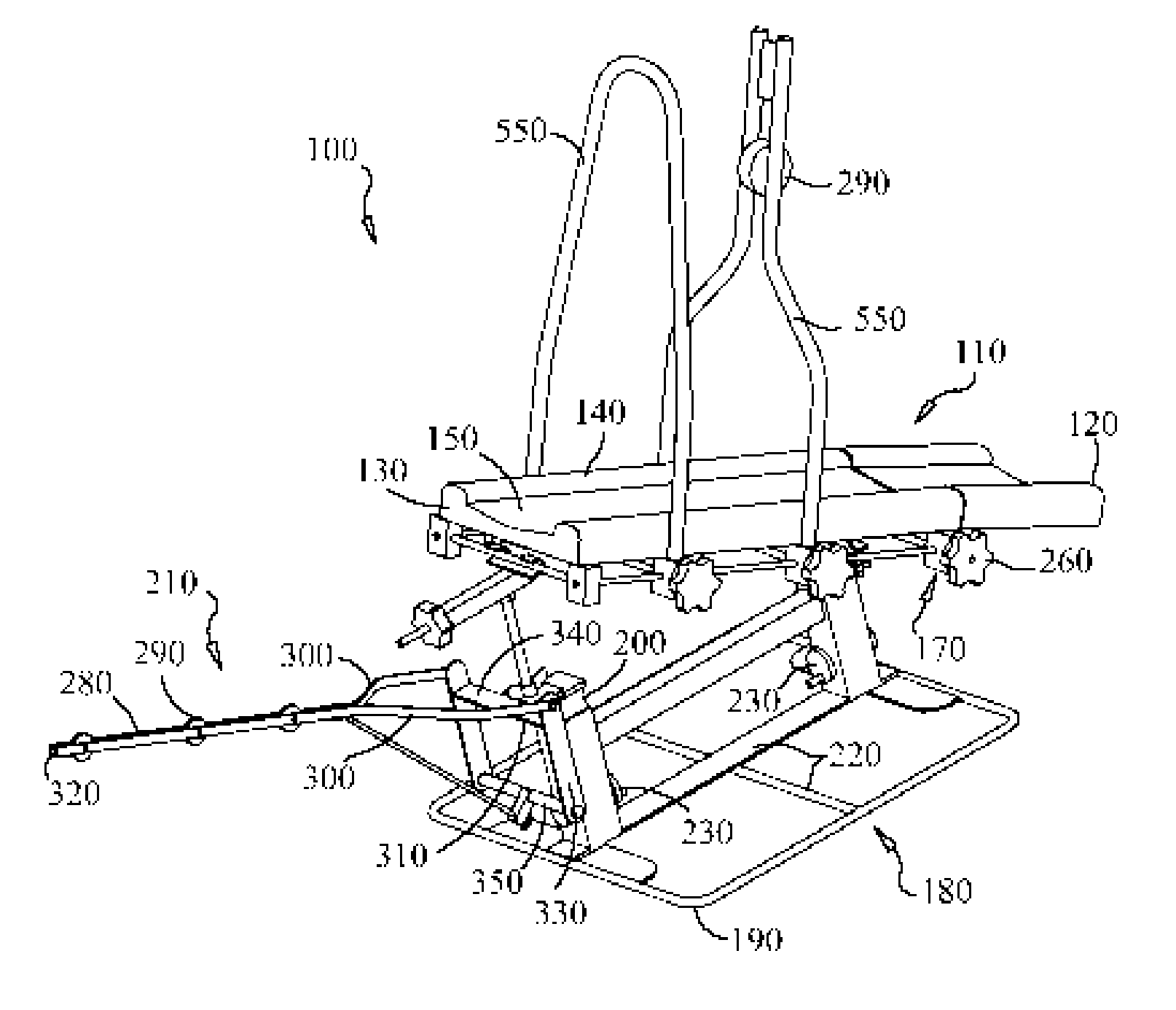
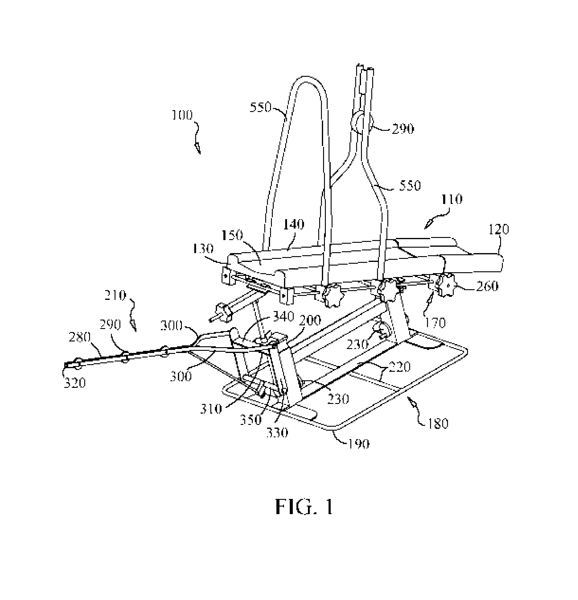
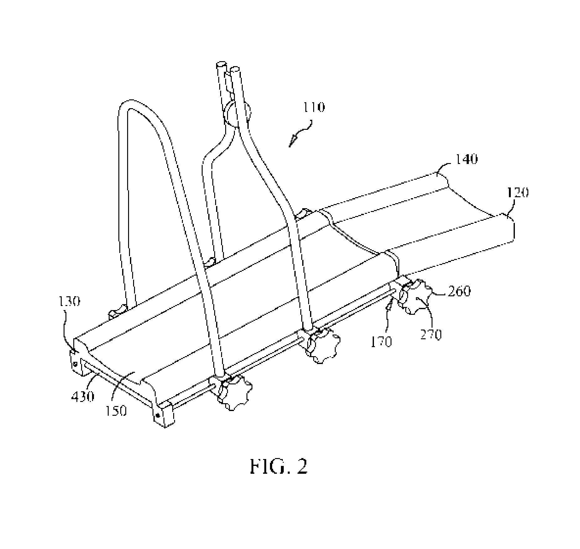
[0033]The portable splint system 100 of the present invention has a limb supporting splint 110 having a proximal end 120 and a distal end 130. FIG. 1 shows a portable splint system 100 according to the present invention. The limb supporting splint 110 has a least two sections, each section has a substantially continuous cover plate 140, each cover plate 140 having a concave contoured upper surface 150 for cradling a splinted limb 160. A locking hinge 170 connects the sections of the limb supporting splint 110. The limb supporting splint 110 is suitable for use in a bed or ove...


PUM


Abstract

A portable splint system is disclosed. The portable splint system has a limb supporting splint having at least two sections, each section has a substantially continuous cover plate, each cover plate having a concave contoured upper surface for cradling a splinted limb. A locking hinge connects the sections of the limb supporting splint. The limb supporting splint may also have one or more vertical support arches mounted thereon. The limb supporting splint is suitable for use in a bed or overhead traction apparatus. The portable splint system also includes a portable base unit onto which the limb supporting splint may be attached. The portable base unit has a stabilizing frame, height adjusters for independently adjusting the height of the proximal end of the limb supporting splint and the distal end of the limb supporting splint, and traction weight supports.

Description

FIELD OF THE INVENTION[0001]The present invention relates to traction splints. Specifically, the present invention relates to portable traction splints.DESCRIPTION OF THE RELATED ART[0002]The use of traction to facilitate the healing of fractured limbs has been practiced for some time. Typically the limb is secured, through the use of bandages, wraps and the like, to a splint. Traction force is applied to the limb through the use of wires, ropes or cables attached to the limb or splint at one end and a weight at the other end. The modern practice of applying traction to fractured limbs dates back to the mid-1800's and Dr. Hugh Owen Thomas. Dr. Thomas advocated the prolonged uninterrupted rest for the treatment of fractures. His “Thomas Splint” was introduced to the battlefields of World War I, where it is credited with the reducing the fatality rate from compound fractures from about eighty percent to about twenty percent.[0003]The Thomas splint consists of a proximal ring that fits...

Claims


Application Information

Patent Timeline
Patent Type & Authority Patents(United States)
IPC IPC(8): A61F5/00
CPCA61F5/0585A61F5/05841A61F5/3769
Inventor COTTON, GERALD
Owner COTTON GERALD
Learn More