Worm and gear traction system for bridge rotating body, and traction method

A worm gear, traction system technology, applied in bridges, bridge construction, erection/assembly of bridges, etc., can solve the problems of insufficient hydraulic and artificial traction power stability, poor traction stability effect, large working space, etc. Application and promotion value, avoid traction lag effect, good stability effect

Inactive Publication Date: 2017-09-05
中铁西南科学研究院有限公司
View PDF6 Cites 4 Cited by
  • Summary
  • Abstract
  • Description
  • Claims
  • Application Information

AI Technical Summary

Problems solved by technology

[0004] At present, the swivel traction method mainly has the following problems: First, the layout and debugging process of the traction system is complicated. Once the traction is started, the swivel process is irreversible; especially after over-rotation, it is difficult to turn in place; the second is that the traction system uses steel strands or wire ropes. It drives the turntable to rotate, which is a flexible transmission and has a transmission hysteresis effect. It cannot achieve continuous and uniform traction before the steel strand or wire rope is tensioned; the third is that the hydraulic and manual traction power stability is relatively insufficient, and the traction stability is not good; It is necessary to pour the traction reaction seat at a certain distance outside the turntable, which requires a large working space and is not suitable for narrow environments

Method used


Image

  • Worm and gear traction system for bridge rotating body, and traction method
  • Worm and gear traction system for bridge rotating body, and traction method
  • Worm and gear traction system for bridge rotating body, and traction method

Examples


Embodiment Construction

[0019] The present invention will be further described below in combination with specific embodiments and accompanying drawings.

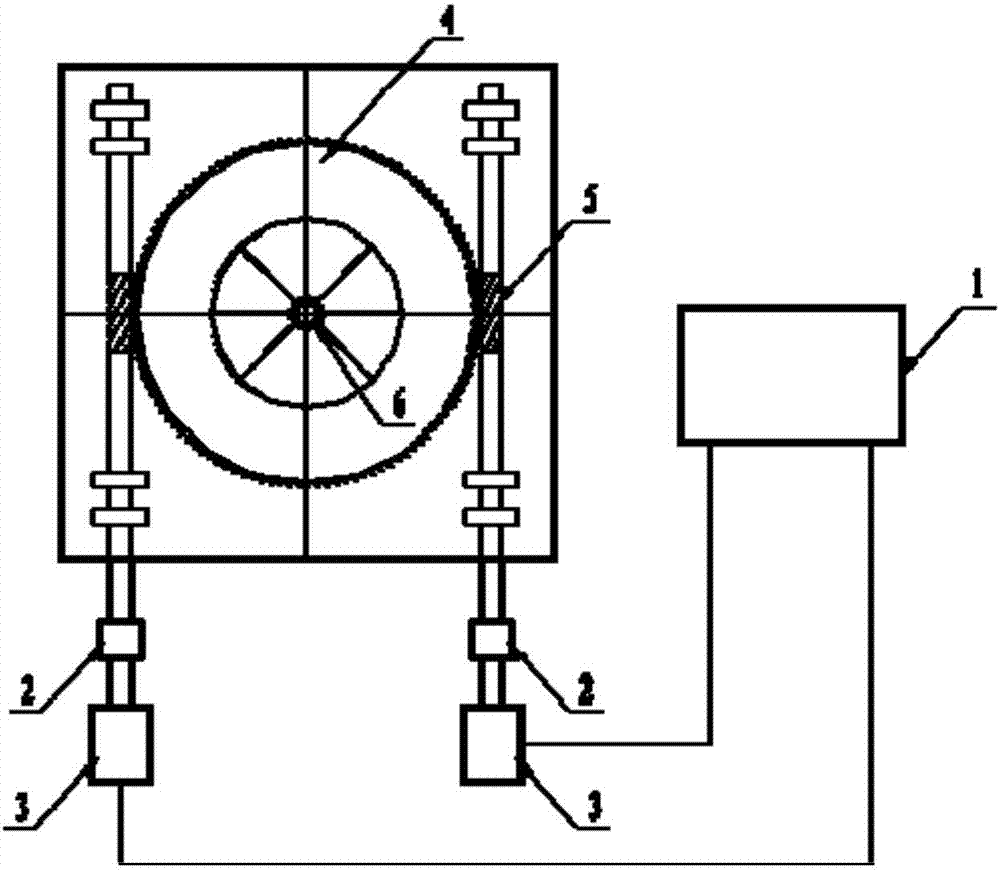
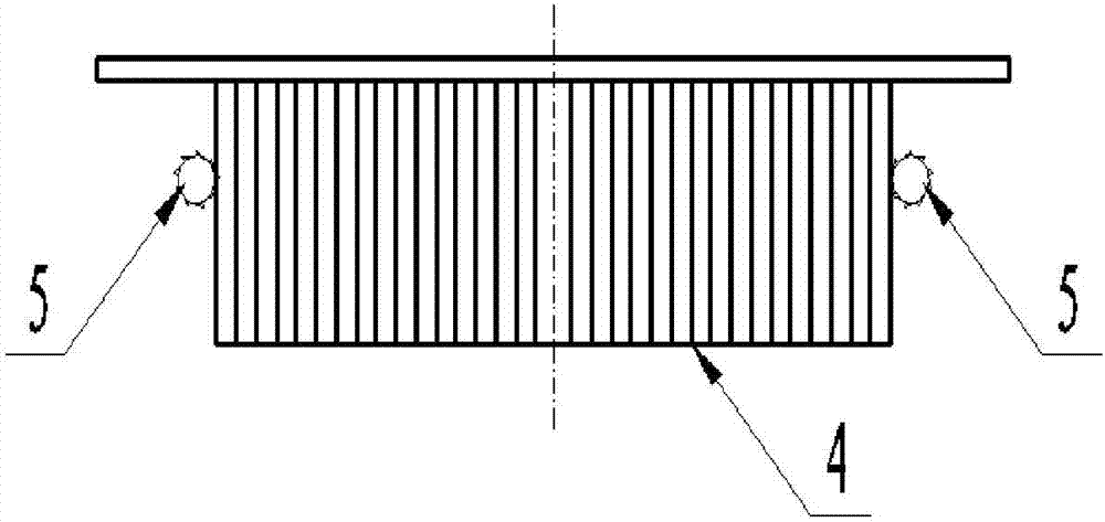
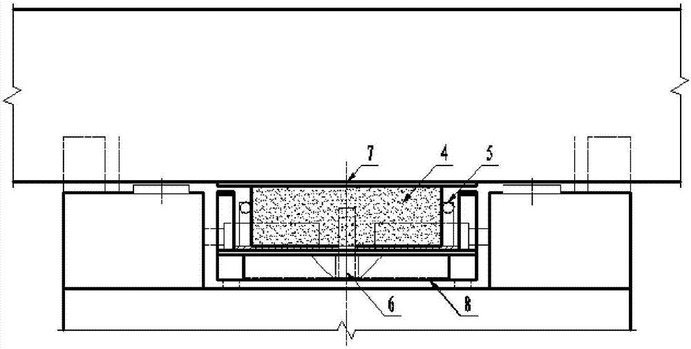
[0020] Such as Figure 1 to Figure 4 As shown, a worm gear traction system of a bridge swivel mainly includes a control system 1, a power system 3, a reduction device 2, a worm wheel 4, a worm 5, an upper turntable 7 and a lower turntable 8, and the control system 1 and the power system 3 circuit connection, the control system 1 is set independently, the power system 3 is set independently or on the lower turntable 8, the power system 3 is connected to the deceleration device 2, the deceleration device 2 is mechanically connected to the worm 4, and the worm gear 4 cooperates with the worm 5 connected, and the worm 5 is two parallel and symmetrically installed on both sides of the worm wheel 4, the hub of the worm wheel 4 is inlaid with the outer ring of the upper turntable 7, and the upper turntable 7 is connected with the lower turntable 8 through...


PUM


Abstract

The invention discloses a worm and gear traction system for a bridge rotating body, and a traction method. The traction system mainly comprises a control system, a power system, a speed reducing device, a worm gear, a worm, an upper swivel plate and a lower swivel plate. The traction method of the traction system comprises the steps of firstly, using the control system to start the power system so as to drive the worm to rotate, enabling the rotation of the worm to be linked with the rotation of the worm gear, driving the upper swivel plate to rotate by means of the rotation of the worm gear, and driving a bridge body to rotate until the rotating body takes place, wherein the rotating speeds of the worm gear and the worm are regulated and controlled by using the control system to adjust the rotating speed of a motor of the power system in a rotating process, so that the speed of the rotating body is regulated and controlled. The worm and gear traction system and the traction method have the advantages that the forward and backward direction traction for a rotating body structure can be realized, so that the demand of traction direction adjustment can be met when a rotation test is carried out and the rotating body is in place; worm drive is rigid drive, so that a traction hysteresis effect can be avoided, and continuous and uniform traction is realized; mechanical transmission traction is adopted, so that the traction system is good in stability.

Description

technical field [0001] The invention relates to the technical field of bridge swivel construction, in particular to a worm gear traction system for a bridge swivel. Background technique [0002] Bridge swivel construction refers to a construction method in which the bridge structure or its main components are poured or assembled at a position other than the design axis, and then put in place by swivel. According to the rotation direction of the bridge structure, it can be divided into vertical rotation construction method, horizontal rotation construction method and the method of combining horizontal rotation and vertical rotation, among which the horizontal rotation method is the most widely used. From the construction of the first Suining Construction Bridge in 1977 to the present, nearly 300 bridges have been built using the swivel construction method across the country, achieving good technical and economic benefits. [0003] The swivel traction mode develops from inter...

Claims


Application Information

Patent Timeline
Patent Type & Authority Applications(China)
IPC IPC(8): E01D21/08
CPCE01D21/08
Inventor 张三峰邱珂曹文陈杨傅贤超康圣雨李冰孙涛丁群峰
Owner 中铁西南科学研究院有限公司
Why Eureka
Try Eureka