Resilient braided rope seal

a braided rope and sealing technology, applied in the direction of engine seals, mechanical devices, engine components, etc., can solve the problems of limiting the ability of prior art seals, none of these prior art seals have properties which perform as well, etc., to achieve improved resiliency, improved resiliency without sacrificing temperature capability, and sufficient resiliency

Inactive Publication Date: 2000-03-21
NAT AERONAUTICS & SPACE ADMINISTATION U S GOVERNMENT AS REPRESENTED BY THE
View PDF10 Cites 100 Cited by
  • Summary
  • Abstract
  • Description
  • Claims
  • Application Information

AI Technical Summary

Benefits of technology

It is a further object of the present invention to provide an improved sealing article for providing a generally low leakage fluid seal between adjacent components which are subject to relative movement, vibrations, internal pressures, and temperature changes.
It is a further object of the present invention to provide an improved resilient sealing article to seal gaps between adjoining components of advanced aerospace engines and vehicles.
It is a further object of the present invention to provide a sealing article capable of remaining resilient at very high temperatures and when exposed to large temperature ...

Problems solved by technology

The seals known in the prior art to have some deficiencies limiting their ability to meet design requirements in applications such as advanced aerospace engines and vehicles, and other applications which require sealing between relatively movable components comprised of dissimilar materials which undergo repeated high...

Method used


Image

  • Resilient braided rope seal
  • Resilient braided rope seal
  • Resilient braided rope seal

Examples


second embodiment

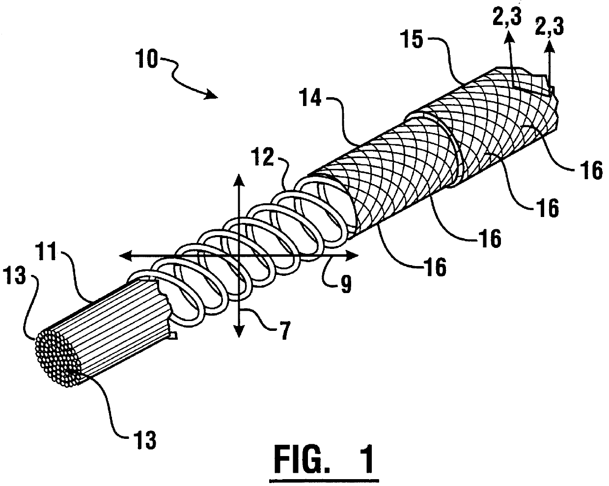
Referring now to FIG. 4, there is shown the invention. This embodiment includes a plurality of coil filler fibers 22 which extend circumferentially around core 11 and intermediate each pair of adjacent coils of spring member 12 in order to fill the longitudinal void between such coils. Filling the space between the coils blocks a potential leakage flow path. Furthermore filling this void reduces the possibility of the resilient spring member 12 causing abrasion to inner sheath 14. As shown in FIG. 4 filler fibers 22 preferably include a plurality of overlying fiber layers which extend outward from adjacent the core to about the height of the coils. Filler fibers 22 are particularly useful where low leakage is required. Fibers 22 may be manufactured of a variety of materials, but in the preferred embodiment are manufactured of a superalloy or ceramic material in order to provide sufficient flow and heat resistance.

third embodiment

Referring now to FIG. 5, there is shown the invention. A fluid passage which in the embodiment shown is a porous cooling tube 32, extends in the core 11. The porous cooling tube 32 in the center of the seal enables the flow of a seal purge gas as shown by arrow A. The use of this central cooling tube is required at axial engine stations where gas temperatures exceed the maximum use temperature of the seal. The seal purge gas pressure also can be used to provide added support and inflate the seal structure increasing preload and enhancing sealing contact with the adjacent seal surfaces.

The porous cooling tube 32 is designed to serve as a manifold for delivering high pressure coolant gas at locations where the surrounding temperatures are higher than the seal material limits. Selecting an inert purge coolant gas such as helium, flowing radially outward through the wall of the seal as indicated by the arrows B, accomplishes two important functions. The gas cools the seals, and it provi...


PUM


Abstract

A resilient braided rope seal for use in high temperature applications includes a center core of fibers, a resilient canted spring member supporting the core and at least one layer of braided sheath fibers tightly packed together overlying the spring member. The seal provides both improved load bearing and resiliency. Permanent set and hysteresis are greatly reduced.

Description

This invention relates to sealing methods and structures. Specifically this invention relates to a sealing article particularly suitable for sealing gaps between adjacent components which are subjected to repeated cycling between extreme temperatures, such as components of advanced aerospace engines and vehicles.Numerous types of seals and sealing methods are known in the prior art. Seals are commonly used for sealing gaps and spaces between adjacent components. In many situations the primary function of the seal is to enable relative movement of the adjacent components while minimizing flow of fluids between such elements. The relatively movable components are commonly subject to static and dynamic forces, including forces produced by relative movement of the components as well as forces produced by vibrations, fluid pressure and thermal expansion and contraction. Numerous factors affect the ability of a seal to effectively seal an area between adjacent components, including enviro...

Claims


Application Information

Patent Timeline
IPC IPC(8): F16J15/08F16J15/12
CPCF16J15/0812F16J15/121
Inventor T
Owner NAT AERONAUTICS & SPACE ADMINISTATION U S GOVERNMENT AS REPRESENTED BY THE
Why Eureka
Try Eureka