Method for controlling the positioning of the synchronizers of a dual clutch transmission

a technology of synchronizer and transmission, which is applied in the direction of mechanical actuator clutch, mechanical apparatus, gearing, etc., can solve the problems of reduced efficiency, drive connection, and large physical interaction of the operator, and achieve accurate and consistent control of the operation.

Inactive Publication Date: 2005-04-26
BORGWARNER INC
View PDF31 Cites 100 Cited by
  • Summary
  • Abstract
  • Description
  • Claims
  • Application Information

AI Technical Summary

Benefits of technology

[0016]One advantage of the present invention is provided in the constant monitoring of the neutral positions of the synchronizers and controlling them while in neutral to avoid a drift condition where a neutralized but errant synchronizer could drift into non-commanded contact with a gear set causing interference and damage. Thus, the method of the present invention not only monitors a neutralized synchronizer to sense if the synchronizers drifts but also corrects its position by moving the synchronizer back to its neutral position if a drift occurs.
[0017]Another advantage of the present invention is provided in the constant monitoring of the engaged positions of the synchronizers and controlling them while engaged to avoid a jumpout event where the synchronizer could slip out of engagement causing damage and loss of control. When any synchronizer is first engaged, the method provides that the synchronizer is moved to a full engagement position then monitors the synchronizer as it operates to transfer torque in the transmission to prevent a jumpout condition. Thus, the method of th

Problems solved by technology

The disadvantages of the manual transmission is that there is an interruption in the drive connection during gear shifting and that there is a great deal of required physical interaction on the part of the operator to shift gears.
Although conventional automatic transmissions avoid an interruption in the drive connection during gear shifting, they suffer from the disadvantage of reduced efficiency because of the need for hydrokinetic devices, such as torque converters, interposed between the output of the engine and the input of the transmission for transferring kinetic energy therebetween.
Fluid couplings have inherent slip.
The inherent slip reduces the efficiency of the torque converter.
While torque converters provide a smooth coupling between the engine and the transmission, the slippage of the torque converter results in a parasitic loss, thereby decreasing the efficiency of the entire powertrain.
The power required to drive the pump and pressurize the fluid introduces additional parasitic losses of efficiency in the automatic transmission.
However, even with the inherent improveme

Method used


Image

  • Method for controlling the positioning of the synchronizers of a dual clutch transmission
  • Method for controlling the positioning of the synchronizers of a dual clutch transmission
  • Method for controlling the positioning of the synchronizers of a dual clutch transmission

Examples


Embodiment Construction

)

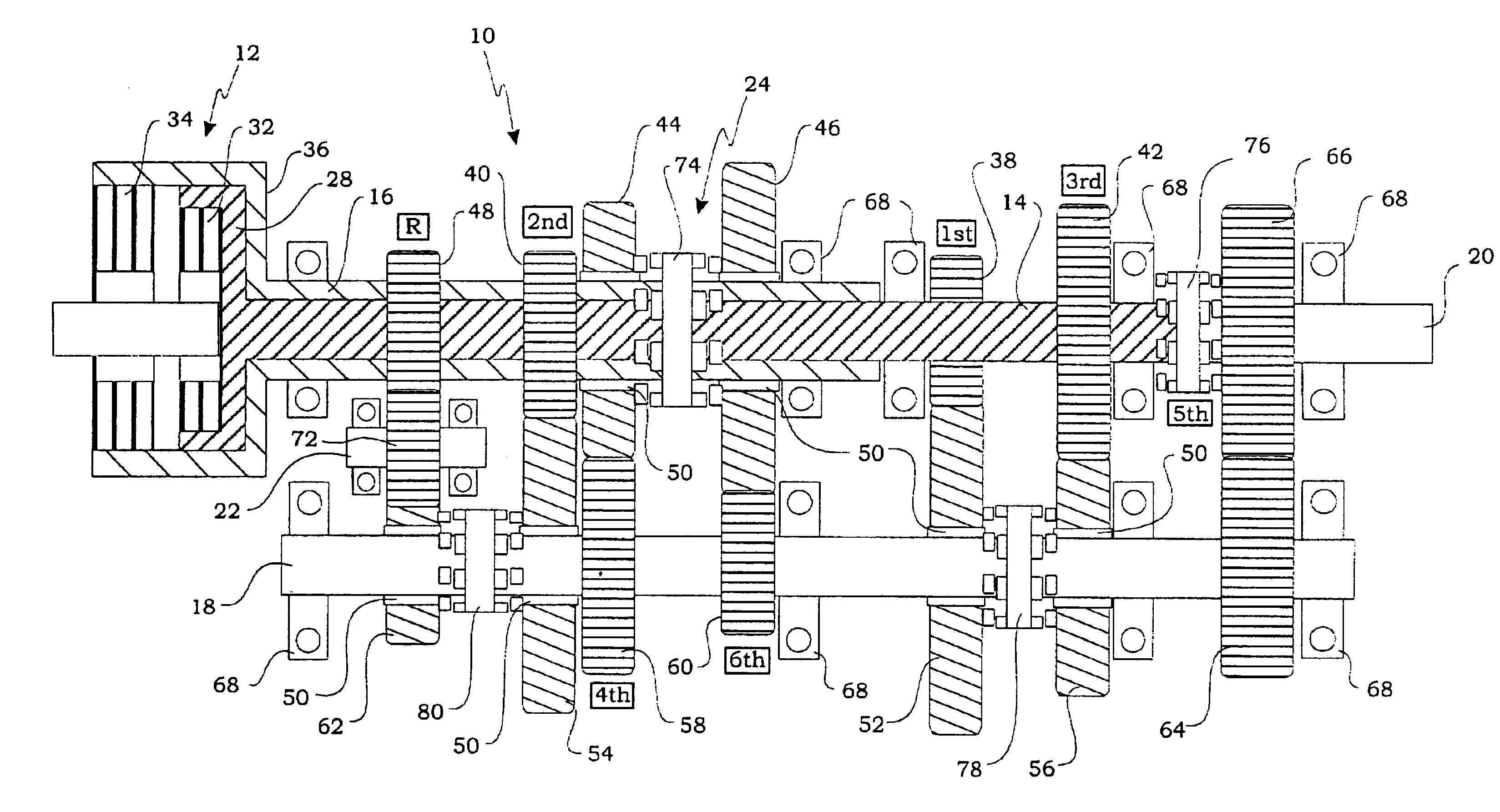
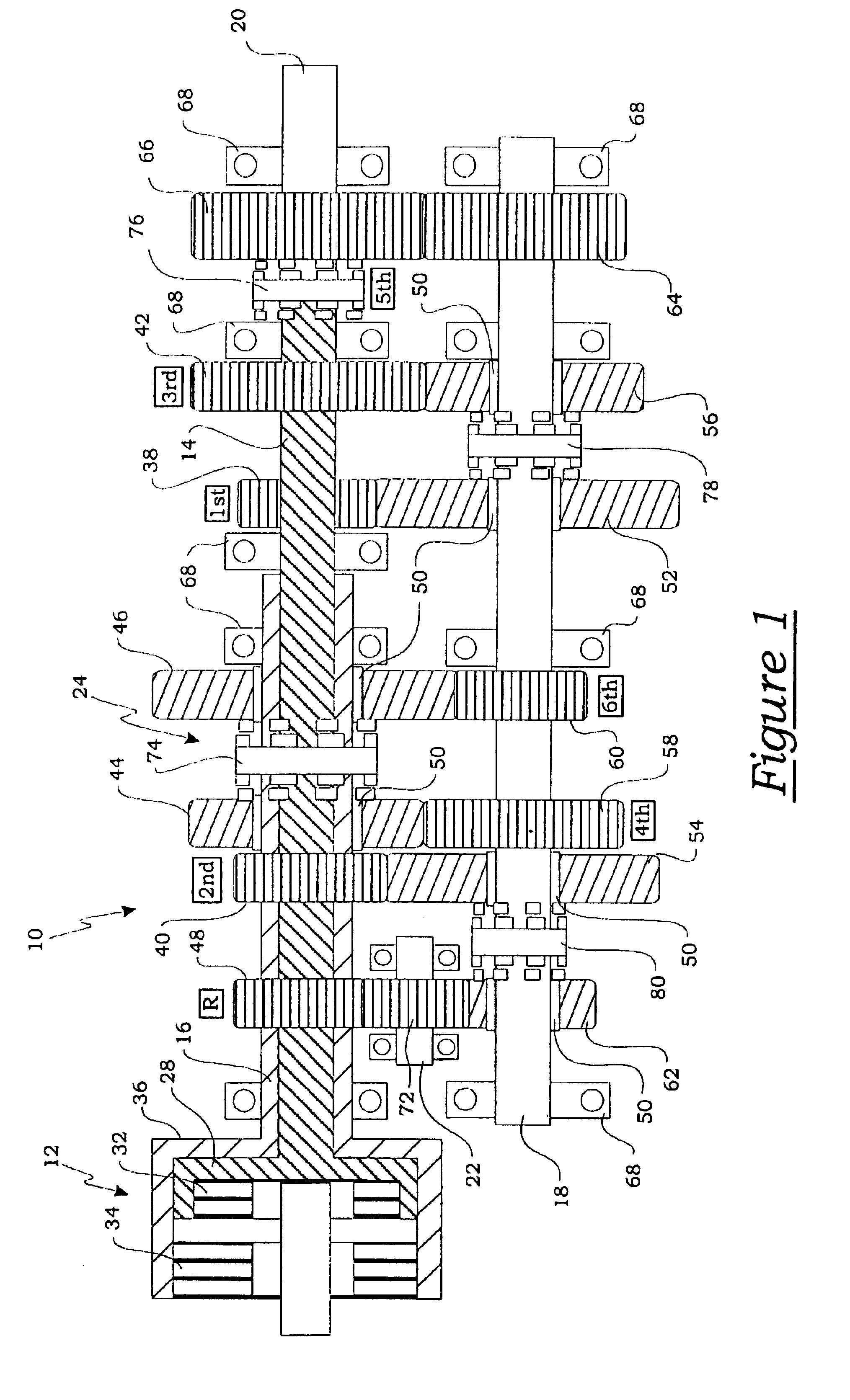
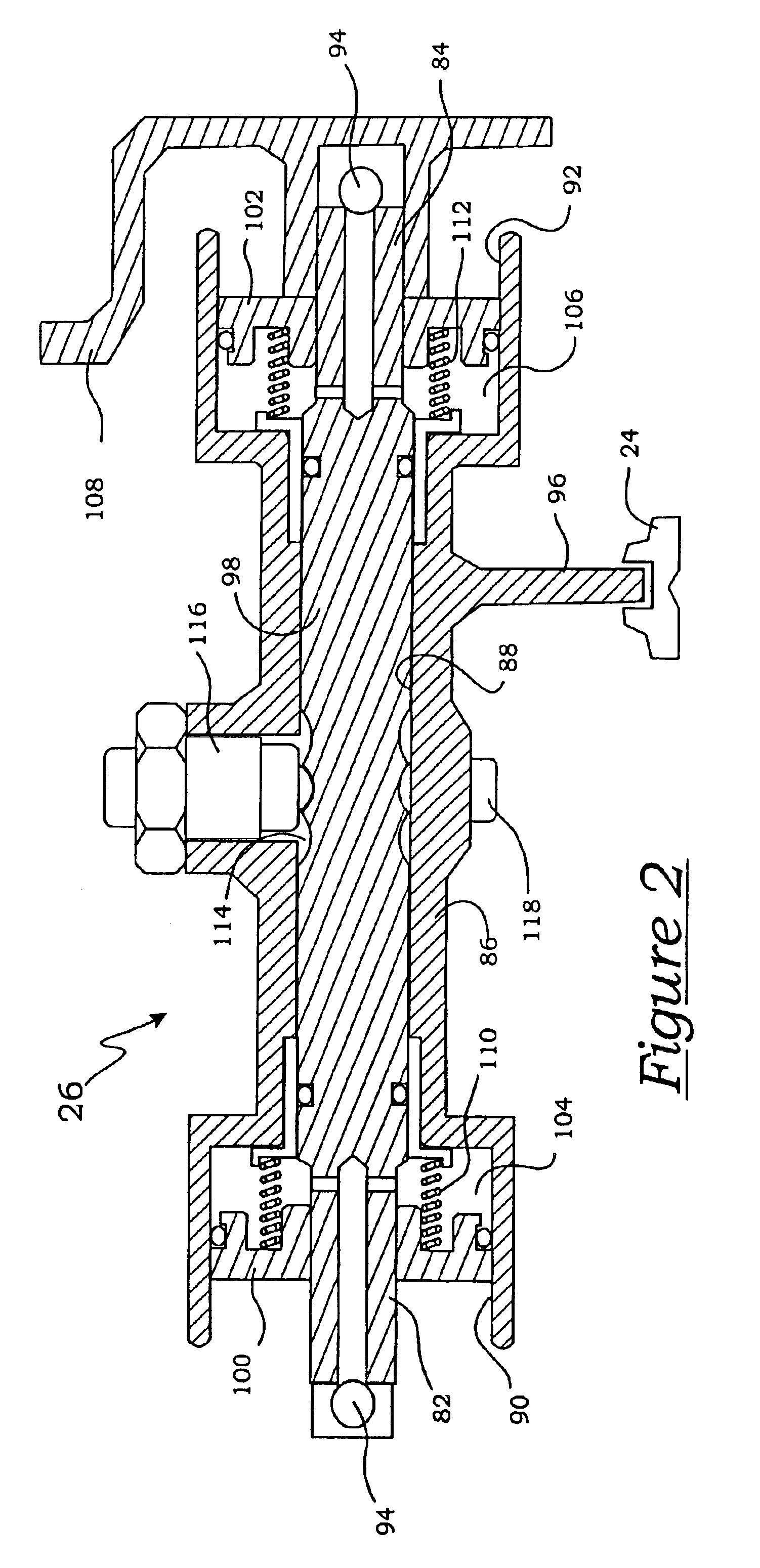
[0027]A representative dual clutch transmission that may be controlled by the present invention is generally indicated at 10 in the schematic illustrated in FIG. 1. Specifically, as shown in FIG. 1, the dual clutch transmission 10 includes a dual, coaxial clutch assembly generally indicated at 12, a first input shaft, generally indicated at 14, a second input shaft, generally indicated at 16, that is coaxial to the first, a counter shaft, generally indicated at 18, an output shaft 20, a reverse counter shaft 22, a plurality of synchronizers, generally indicated at 24, and a plurality of shift actuators generally indicated at 26 (FIG. 2).

[0028]The dual clutch transmission 10 forms a portion of a vehicle powertrain and is responsible for taking a torque input from a prime mover, such as an internal combustion engine and transmitting the torque through selectable gear ratios to the vehicle drive wheels. The dual clutch transmission 10 operatively routes the applied torque from the eng...


PUM


Abstract

A method of controlling the positioning of the synchronizers of a dual clutch transmission having a plurality of synchronizers to selectively engage and disengage various gears sets, and a plurality of shift actuators adapted to move the synchronizers. The method includes the steps of initiating a control routine to move a synchronizer to a full engagement position with a gear set and monitoring the positions of all engaged synchronizers. The method also includes reinitiating the control routine to move a synchronizer back into the full engagement position when any engaged synchronizer slips out to a minimum engagement position. Further, the method includes initiating a control routine to move a synchronizer to a neutral position and monitoring the position of all disengaged synchronizers. Also, reinitiating the control routine to move a synchronizer back to the neutral position when any disengaged synchronizer drifts beyond a pre-determined neutral hysteresis position.

Description

BACKGROUND OF THE INVENTION[0001]1. Field of the Invention[0002]The present invention relates, generally to the control of a dual clutch transmission and, more specifically, to a method for actively controlling the positioning of the synchronizers of a dual clutch transmission for use in a motor vehicle driveline.[0003]2. Description of the Related Art[0004]Generally speaking, land vehicles require a powertrain consisting of three basic components. These components include a power plant (such as an internal combustion engine), a power transmission, and wheels. The power transmission component is typically referred to simply as the “transmission.” Engine torque and speed are converted in the transmission in accordance with the tractive-power demand of the vehicle. Presently, there are two typical transmissions widely available for use in conventional motor vehicles. The first, and oldest type is the manually operated transmission. These transmissions include a foot operated start-up ...

Claims


Application Information

Patent Timeline
IPC IPC(8): F16H61/28F16H61/30F16H59/68F16H61/12F16D25/12F16D23/06F16D48/02F16H61/02F16H61/688
CPCF16H61/2807F16H61/30F16H61/688F16H2059/6807Y10T74/19233F16H2061/1228F16H2061/283Y10T74/19251Y10T74/19228F16H2061/1208F16D23/06
Inventor KOENIG, MELISSAFIRTH, DARRENBUCHANAN, MARK
Owner BORGWARNER INC
Why Eureka
Try Eureka