Devices and methods of operation thereof for providing stable flow for centrifugal compressors

a centrifugal compressor and flow control technology, applied in the direction of machines/engines, engine starters, liquid fuel engines, etc., can solve the problems of inability to maintain stable operation of centrifugal compressors, and inability to maintain pressure and flow. stable operation, the effect of preventing stalling and surge conditions

Inactive Publication Date: 2008-02-05
NASA
View PDF25 Cites 74 Cited by
  • Summary
  • Abstract
  • Description
  • Claims
  • Application Information

AI Technical Summary

Benefits of technology

[0010]It is a primary objective of the invention to provide devices and methods of operation thereof that can be employed for the purpose of maintaining stable operation of a centrifugal compressor by preventing stall and surge conditions therein.
[0014]The invention is directed to devices and methods of operation thereof for controlling the flow within a diffuser of a compressor so as to prevent or eliminate flow instabilities of the compressor that might otherwise cause rotating stall and surge conditions in the compressor itself.
[0015]A centrifugal compressor comprises an impeller that rotates inside a stationary flow path that is typically formed by an inlet, a shroud, a diffuser and a discharge duct. The impeller is comprised of a plurality of blades attached to a hub that is rotated by a shaft and is contained within a stationary shroud. The impeller receives an input fluid and imparting kinetic energy to the received fluid provides an output thereof in an orthogonal direction relative to the axis of rotation. The output of the impeller is received by a diffuser having blades or vanes contained within hub and shroud end-walls wherein kinetic energy contained within the received fluid is recovered providing an increase in static pressure of the received fluid. At least one flow stabilizing device is inserted into the diffuser for the purpose of maintaining or restoring compressor stability.

Problems solved by technology

Local oscillations of pressure disadvantageously occur within the compressor and adjacent components.
Time-averaged supplies of pressure and flow to downstream processes are undesirably diminished.
More particularly, catastrophic damage to the centrifugal compressor and adjacent components can result from pressure and flow oscillations.
Further, downstream processes are disrupted with potentially serious consequences.
In the case of a turbine engine, the production of thrust or shaft-horsepower is severely reduced or stopped altogether.
The flow-field instability leading to surge can develop in either the impeller or diffuser of the compressor, with diffuser initiated surge being the more severe case.
As such, it is difficult to prescribe a single solution.
There is little prior art to address the problem of controlling stall and surge in centrifugal compressors.
Hence, losses produced by this technique must be endured when stability enhancement is not required.
Variable geometry of diffusers is expensive to implement, as it requires numerous complex parts.
Further, it disadvantageously activates slowly compared to the onset of stall and surge.
Bleeding process flow reduces process efficiency since work that has gone into pressurizing the flow is disadvantageously lost with the bleed-flow.
Piping to deliver air at the injection points disadvantageously adds weight and complexity to an engine.
As such, air injection techniques may be limited to ground based centrifugal compression systems, thereby reducing the possible commercial applications thereof.

Method used


Image

  • Devices and methods of operation thereof for providing stable flow for centrifugal compressors
  • Devices and methods of operation thereof for providing stable flow for centrifugal compressors
  • Devices and methods of operation thereof for providing stable flow for centrifugal compressors

Examples


Embodiment Construction

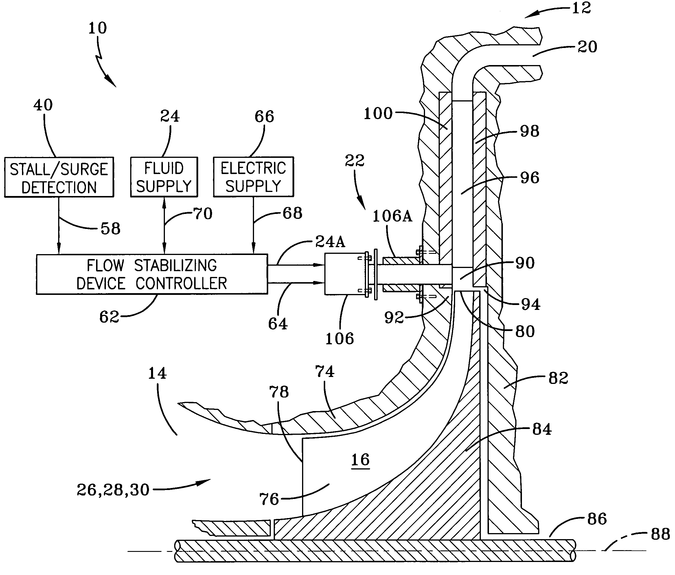
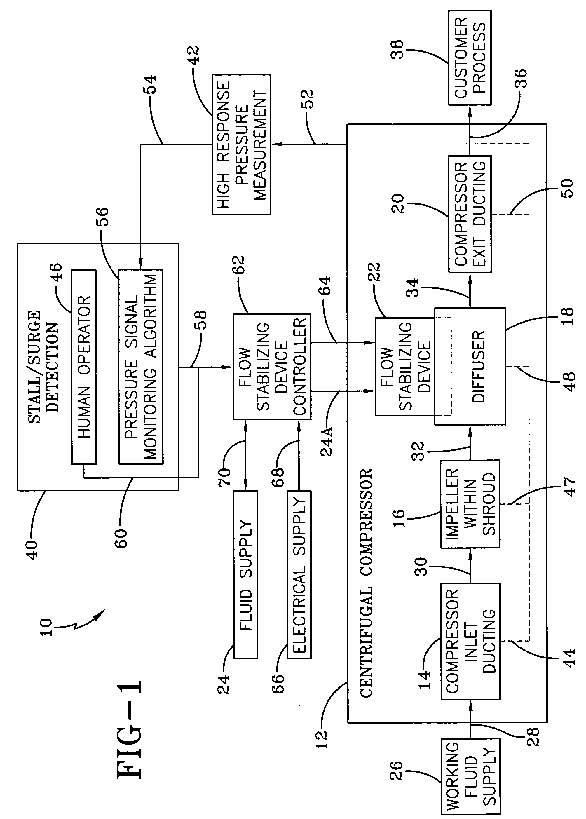
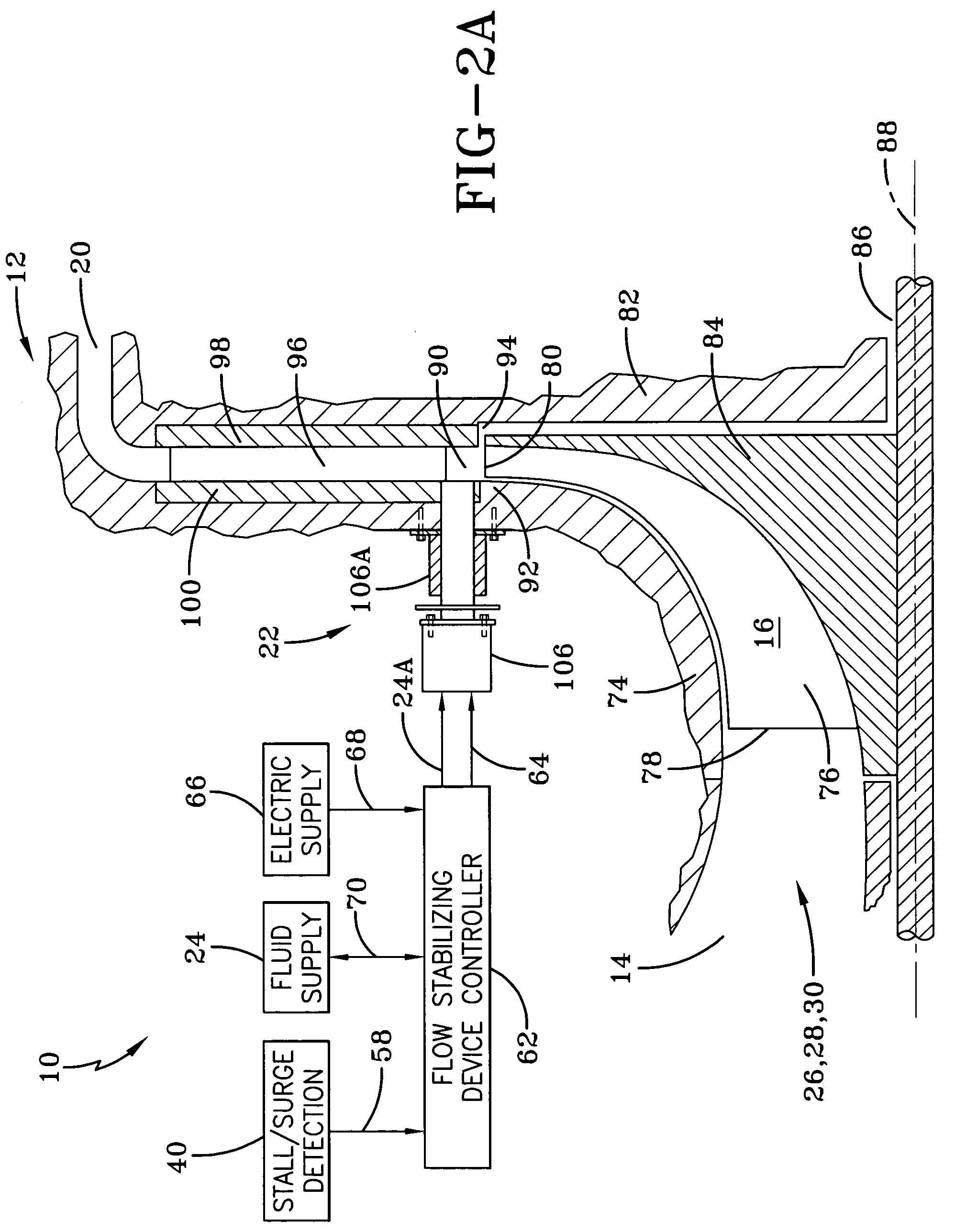
[0030]Referring to the drawings wherein the same reference number is used to identify the same element throughout there is shown in FIG. 1 a block diagram of the system 10 of the present invention particularly suited for a centrifugal compressor 12.

[0031]The centrifugal compressor 12 comprises compressor inlet ducting 14, an impeller 16, which in one embodiment, to be further described hereinafter, is within a shroud, a diffuser 18, and compressor exit ducting 20. The centrifugal compressor 12 is operatively controlled by at least one flow stabilizing device 22, so as to prevent or eliminate flow instabilities of the compressor 12 that might otherwise cause rotating stall and surge conditions in the compressor 12 itself.

[0032]The flow stabilizing device 22 has various embodiments, such as 22A and 22B, that employ actuated or stationary rods. The flow stabilizing device has additional embodiments 22C, 22D, and 22E that utilize a fluid injection valve. Different embodiments of the flo...


PUM


Abstract

Centrifugal compressor flow stabilizing devices and methods of operation thereof are disclosed that act upon the flow field discharging from the impeller of a centrifugal compressor and modify the flow field ahead of the diffuser vanes such that flow conditions contributing to rotating stall and surge are reduced or even eliminated. In some embodiments, shaped rods and methods of operation thereof are disclosed, whereas in other embodiments reverse-tangent air injection devices and methods are disclosed.

Description

ORIGIN OF THE INVENTION[0001]The invention described herein was made by employees of the United States Government and may be used by or for the Government for governmental purposes without payment of any royalties thereon or therefor.FIELD OF THE INVENTION[0002]The present invention relates to centrifugal compressors and, more particularly, to devices and methods of operation thereof that reduce the threat of flow instabilities, commonly known as rotating stall and surge conditions, that can develop in centrifugal compressors used in turbine engines and industrial processes.BACKGROUND OF THE INVENTION[0003]The objective of a centrifugal compressor is to collect a steadily flowing stream of gas, pressurize the stream, and provide a steady pressurized stream to a subsequent process or device used in turbine engines and industrial processes. Instability can develop within the fluid being processed by a centrifugal compressor that interrupts the steady flow of fluid through the compress...

Claims


Application Information

Patent Timeline
Patent Type & Authority Patents(United States)
IPC IPC(8): F01D17/08
CPCF04D27/0207F04D27/0246F04D27/0253F04D27/0238F04D29/444F05D2250/52F04D29/684F04D29/462
Inventor SKOCH, GARY J.STEVENS, MARK A.JETT, THOMAS A.
Owner NASA
Why Eureka
Try Eureka