Current-limiting circuitry

a current-limiting circuit and circuit technology, applied in the field of integrated circuits, can solve problems such as unsatisfactory output instability, and achieve the effect of preventing excessive current flow through the

Active Publication Date: 2006-03-21
MICREL
View PDF3 Cites 76 Cited by
  • Summary
  • Abstract
  • Description
  • Claims
  • Application Information

AI Technical Summary

Benefits of technology

[0014]According to an embodiment of the invention, a FET driver circuit includes an error amplifier for driving a FET, a circuit for providing a reference voltage to the error amplifier, and a current limiting amplifier for preventing excessive current flow through the FET. A feedback loop coupled between an output of the FET and an input of the error amplifier allows the error amplifier to control the FET to produce a desired output voltage.
[0015]Meanwhile, the current limiting amplifier compares a voltage drop across a sense resistor in the path of the FET with a reference voltage drop. If the voltage drop across the sense resistor exceeds the reference voltage drop, the current limiting amplifier generates an overcurrent signal. The overcurrent signal is used, in a coordinated fashion, both to reduce the voltage provided to the FET, thereby reducing the FET output, and to reduce the reference voltage provided to the input of the error amplifier, thereby preventing open loop (unstable) conditions within the FET driver circuit.
[0017]According to another embodiment of the invention, a low dropout voltage regulator (LDO) incorporating the FET driver circuit of the invention can be used to regulate the output of a switching regulator. Rather than use large numbers of capacitors at the output of the switching regulator, an LDO (or group of LDOs) can be used to eliminate the ripple inherent in the output of conventional switching regulators. An additional benefit is the robust overcurrent protection provided by the current limiting circuitry in the LDO(s).

Problems solved by technology

Unfortunately, the overcurrent protection provided by conventional FET driver circuit 100 can create undesirable output instability.

Method used


Image

  • Current-limiting circuitry
  • Current-limiting circuitry
  • Current-limiting circuitry

Examples


Embodiment Construction

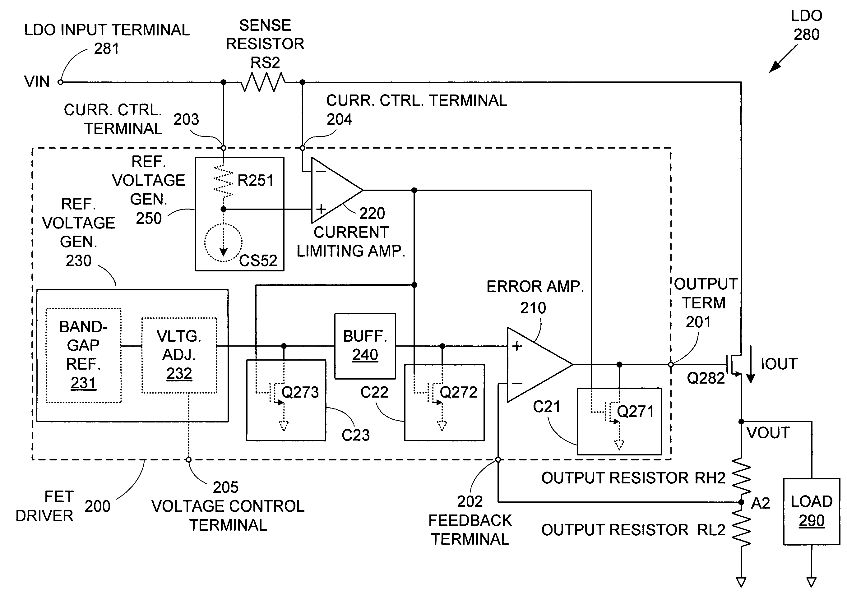
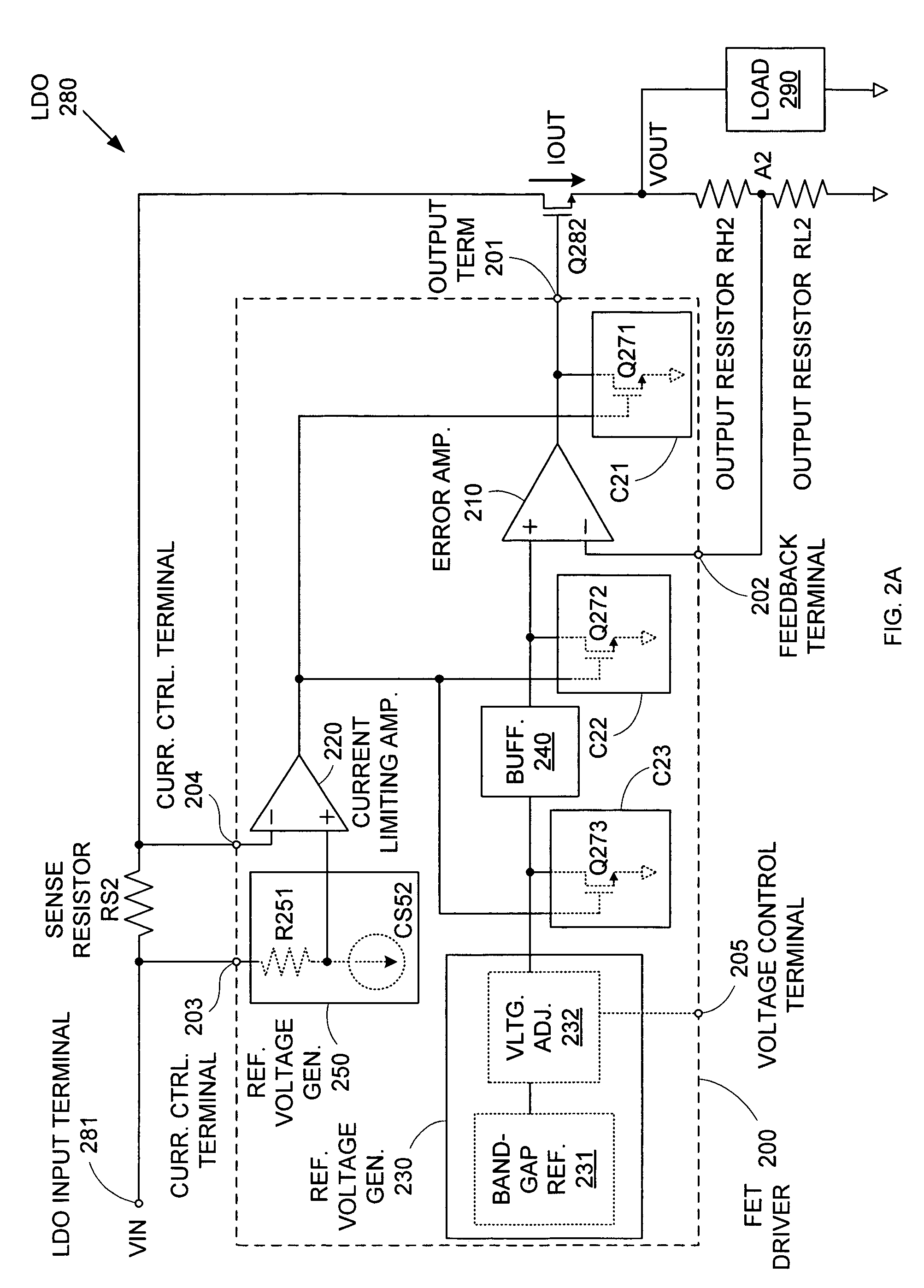
[0022]FIG. 2A shows an LDO 280 in accordance with an embodiment of the invention. LDO 280 includes a LDO input terminal 281, a sense resistor RS2, a pass device, which in this case is an NMOS power transistor Q282, output resistors RH2 and RL2, and a FET driver circuit 200 with overcurrent protection in accordance with an embodiment of the invention. Sense resistor RS2, power transistor Q282, output resistor RH2, and output resistor RL2 are serially connected between LDO input terminal 281 and ground. FET driver circuit 200 controls power transistor 282 so that an input voltage VIN at LDO input terminal 281 is regulated down to a desired voltage VOUT that is supplied to a load 290 at the source of power transistor Q282. Note that, “ground” voltage can refer to any supply voltage lower than input voltage VIN.

[0023]FET driver circuit 200 includes an output terminal 201, a feedback terminal 202, current control terminals 203 and 204, an optional voltage control terminal 205, an error a...


PUM


Abstract

A field effect transistor (FET) driver circuit includes an error amplifier for providing a FET control signal and a current limiting amplifier for preventing excessive current flow through the FET. The current limiting amplifier generates an overcurrent signal when an excessive current is detected. In response to the overcurrent signal, a voltage control circuit adjusts the voltage at the output of the error amplifier to turn off the FET. Meanwhile, a pulldown circuit at an input of the error amplifier adjusts the voltage provided to that input to cause the error amplifier to provide an output voltage that also tends to turn off the FET. If a buffer is present at that input to the error amplifier, a second pulldown circuit is placed at the input to the buffer to maintain a stable unity gain across the buffer.

Description

BACKGROUND OF THE INVENTION[0001]1. Field of the Invention[0002]The invention relates to integrated circuits, and in a particular example to a field effect transistor driver circuit with overcurrent protection.[0003]2. Related Art[0004]Modern power circuits typically incorporate one or more power transistors that are regulated to provide desired voltage and current outputs. Typically, such power transistors are field effect transistors (FETs) that are controlled by dedicated FET driver circuits.[0005]For example, a low dropout voltage regulator (LDO) is a circuit used to minimize the difference between an input supply voltage and a regulated output voltage provided by a FET power transistor, in particular an NMOS power transistor. FIG. 1 shows an LDO 180 that includes an LDO input terminal 181, a sense resistor RS1, an NMOS power transistor Q182, output resistors RH1 and RL1, and a conventional FET driver circuit 100. Sense resistor RS1, power transistor Q182, output resistor RH1, a...

Claims


Application Information

Patent Timeline
Patent Type & Authority Patents(United States)
IPC IPC(8): G05F1/569G05F1/565G05F3/04
CPCG05F1/565Y10S323/908
Inventor MORAVEJI, FARHOODMOHTASHEMI, BEHZAD
Owner MICREL
Why Eureka
Try Eureka