Systems for delivering conditioned air to personal breathing zones

a technology of conditioned air and breathing zone, which is applied in the field of systems for delivering conditioned air to personal breathing zone, can solve the problems that individuals within the area of the unit may not experience all of the beneficial effects of this particle removal, and achieve the effect of improving air quality and improving air quality

Inactive Publication Date: 2006-05-02
HALO INNOVATIONS
View PDF38 Cites 67 Cited by
  • Summary
  • Abstract
  • Description
  • Claims
  • Application Information

AI Technical Summary

Benefits of technology

[0010]The invention provides a system to significantly improve the air quality in a personal breathing environment. Air quality can be improved by one or more of the following: removing allergens and other harmful particles from an air stream prior to the air stream reaching the personal breathing environment; preventing allergens and other harmful particles from reaching the personal breathing environment; and conditioning the air in the personal breathing environment.
[0011]The invention comprises a blower unit, a delivery system that delivers air provided by the blower unit to a person's breathing zone, and a conduit that interconnects the blower unit and the delivery system for directing air from the blower unit to the delivery system. The delivery system is positioned so that it sends conditioned air around a persons head and into their personal breathing zone. The air delivered by the delivery system creates a zone of conditioned air around the persons head. Allergens and other harmful particles are prevented from entering the zone of conditioned air, so that the air being breathed in by the person is substantially the conditioned air delivered by the delivery system.

Problems solved by technology

However, individuals within the area of the unit may not experience all of the beneficial results of this particle removal because the air that is discharged from the unit is able to pick up additional harmful particles from the surrounding environment prior to reaching and being breathed in by the individuals.

Method used


Image

  • Systems for delivering conditioned air to personal breathing zones
  • Systems for delivering conditioned air to personal breathing zones
  • Systems for delivering conditioned air to personal breathing zones

Examples


Embodiment Construction

)

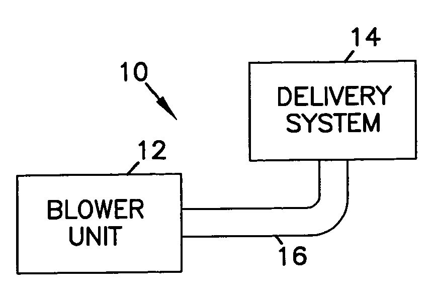
[0040]The present invention, as schematically depicted in FIG. 1, provides a system 10 for delivering conditioned air around one or more person's head, i.e. in their personal breathing zone. The system 10 includes a blower unit 12, a delivery system 14, and a conduit 16 that interconnects the blower unit 12 and the delivery system 14 for directing air from the blower unit to the delivery system.

[0041]The blower unit 12 is preferably provided with a high efficiency filter which filters the air prior to being delivered to the breathing zone. The air can also be conditioned in other manners, for example by one or more of heating or cooling the air, humidifying the air, introducing aromas and medicines into the air, and other conditioning. The delivery system 14 is preferably arranged near a persons head so that it delivers the conditioned air around the person's head and into their personal breathing zone, thereby improving the quality of the air that is breathed by the person. In add...


PUM

PropertyMeasurementUnit
arc angleaaaaaaaaaa
arc angleaaaaaaaaaa
arc angleaaaaaaaaaa

Abstract

A system to significantly improve the air quality in a personal breathing environment. The system includes a blower unit that produces a conditioned air flow, a delivery system that delivers air provided by the blower unit to a person's breathing zone, and a conduit that interconnects the blower unit and the delivery system for directing conditioned air from the blower unit to the delivery system. The delivery system is positioned so that it sends conditioned air around an individual's head and into the individual's personal breathing zone, thereby creating a zone of conditioned air around the individual's head.

Description

[0001]This application claims the benefit Provisional Application Ser. No. 60 / 461,306 filed on Apr. 8, 2003, and claims the benefit of Provisional Application Ser. No. 60 / 539,360 filed on Jan. 27, 2004.FIELD OF THE INVENTION[0002]This invention relates to systems for delivering conditioned air to personal breathing zones. More particularly, this invention relates to systems in the personal environment that deliver conditioned air to improve health or comfort.BACKGROUND OF THE INVENTION[0003]Asthma in the U.S. and around the world has increased at an alarming rate over the last 20 years and currently affects more than 15 million Americans. There is some speculation as to the cause of this increase, whether due to more time spent indoors in “tighter” homes with less fresh air or because of improvements in early diagnosis of disease. A recent study concluded that the risk due to residential allergen and pollutant exposure accounted for 39% of doctor-diagnosed asthma in U.S. children le...

Claims


Application Information

Patent Timeline
Patent Type & Authority Patents(United States)
IPC IPC(8): F24F3/16A47C21/04A61F7/00F24F1/0073
CPCA47C21/044F24F3/1607A61F2007/006A61F2007/0094F24F2221/38F24F2001/0096F24F2221/12F24F1/0071F24F3/163F24F1/0073F24F2221/10
Inventor SCHMID, WILLIAM R.HACKER, DEAN W.KRAUSE, ERIC J.
Owner HALO INNOVATIONS
Why Eureka
Try Eureka