Engine tail gas after-treatment control system and control method

A technology of exhaust gas post-treatment and control system, which is applied to the electronic control of exhaust treatment devices, exhaust treatment, engine components, etc. It can solve the problems of large measurement results, uncontrollable closed-loop strategy, ammonia cross-sensitivity, etc., and achieve enhanced Robustness, improving calculation accuracy and execution efficiency, and reducing pollution

Inactive Publication Date: 2019-09-06
三河市科达科技有限公司
View PDF8 Cites 36 Cited by
  • Summary
  • Abstract
  • Description
  • Claims
  • Application Information

AI Technical Summary

Problems solved by technology

Since the SCR catalyst can store a large amount of ammonia (NH 3 , the ammonia will be released during the sudden change from low temperature to high temperature. This process cannot be controlled by any closed-loop strategy, and only feedback control can not achieve good results. Moreover, the current commercial nitrogen oxide (NOx) sensor still has ammonia The problem of cross-sensitivity, that is, in the presence of ammonia, the NH 3 As NOx, the measurement result is too large, so there are still some problems when used as a closed-loop control
Ammonia sensor is currently under development and has not yet been mass-produced

Method used


Image

  • Engine tail gas after-treatment control system and control method
  • Engine tail gas after-treatment control system and control method

Examples


Embodiment Construction

[0028] In order to make the purpose of the present invention, technical solutions and advantages clearer and more intuitive, the following will be combined with the present invention figure 1 and figure 2 , to clearly and completely describe the present invention.

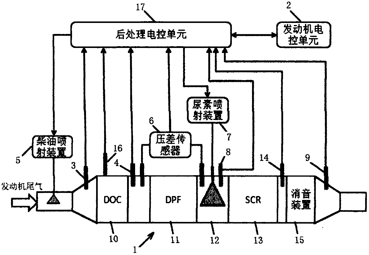
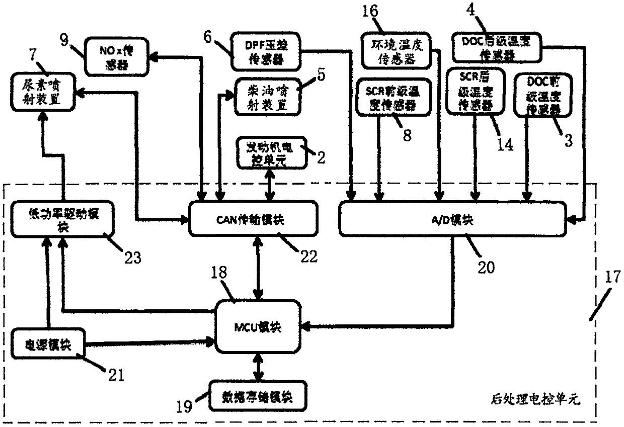
[0029] In the first aspect, the present invention proposes an engine exhaust post-treatment control system, including an exhaust post-processor 1 , an engine electronic control unit 2 , a diesel injection device 5 , a urea injection device 7 , and an after-treatment electronic control unit 17 .

[0030]The exhaust gas post-processor 1 is connected to the exhaust pipe. In the exhaust gas post-processor 1, DOC10, DPF11, mixing chamber 12, SCR13 and muffler device 15 are packaged sequentially from front to back. Several sensors are installed on the exhaust gas post-processor 1 . The injection head of described diesel injection device 5 is installed in the exhaust pipe of DOC10 front end, and diesel oil is injected...


PUM


Abstract

The invention provides an engine tail gas after-treatment control system and control method. The engine tail gas after-treatment control system and control method are applied to after-treatment of tail gas. The control system comprises a tail gas post-processor, an engine electric control unit, a diesel injection device, a urea spraying device and a post-treatment electric control single element.The control method is based on the measured values of different sensors and the working condition parameters of an engine, and is based on a pre-calibrated data model to complete the four functions ofDPF active regeneration controlling, DPF accumulated dust cleaning, SCR urea injection controlling and system fault diagnosing. The system is composed of a software system and a hardware system, wherein a transient segmented linear interpolation algorithm is adopted for MAP data, and the calculation precision and the execution efficiency are improved to a great extent. A DPF differential pressuresensor adopts a differential pressure dynamic integral and time-sharing comparison method, so that the condition that the differential pressure value is unstable and the fluctuation is large due to the fact that the differential pressure sensor is influenced by various factors is solved, the robustness of a control strategy of the tail gas after-treatment system is enhanced, and the misjudgment of regeneration is reduced to a great extent, so that the improper active regeneration operation is reduced, and the oil consumption is reduced.

Description

technical field [0001] The invention belongs to the technical field of diesel engines, is applied to an exhaust after-treatment system, and mainly relates to the technical route "DOC+DPF+SCR" for exhaust emission control. Background technique [0002] In order to meet the increasingly stringent diesel engine / vehicle exhaust emission standards, it is not only necessary to innovate and improve the engine technology of diesel engines / vehicles, but also to adopt exhaust after-treatment technology to ensure that the emission value of pollutants is controlled within a reasonable range and reduce the emission of diesel engines. The emission of pollutants will pollute the environment, meet the legal tail gas emission standards, and improve the ambient air quality. [0003] The "Technical Requirements for Pollutant Emission Control of Non-road Mobile Machinery and Its Equipped Diesel Engines" (Draft for Comment) formulated by the Ministry of Environmental Protection has added the emi...

Claims


Application Information

Patent Timeline
Patent Type & Authority Applications(China)
IPC IPC(8): F01N3/20F01N3/28F01N3/025F01N9/00F01N11/00
CPCF01N3/0253F01N3/2066F01N3/208F01N3/28F01N9/00F01N9/002F01N11/002F01N2610/02Y02T10/12Y02T10/40
Inventor 李会利王广起
Owner 三河市科达科技有限公司
Why Eureka
Try Eureka