Ventilator system for recirculation of air and regulating indoor air temperature

a technology of air circulation and ventilation system, which is applied in ventilation system, lighting and heating apparatus, heating types, etc., can solve the problems of high energy cost of industrial and commercial environments, poor air circulation efficiency of conventional hvac system, and inefficient hvac system, so as to improve comfort, improve air quality, and eliminate the effect of ceiling fan drafts

Inactive Publication Date: 2012-03-01
CLAWSEY MARK
View PDF27 Cites 36 Cited by
  • Summary
  • Abstract
  • Description
  • Claims
  • Application Information

AI Technical Summary

Benefits of technology

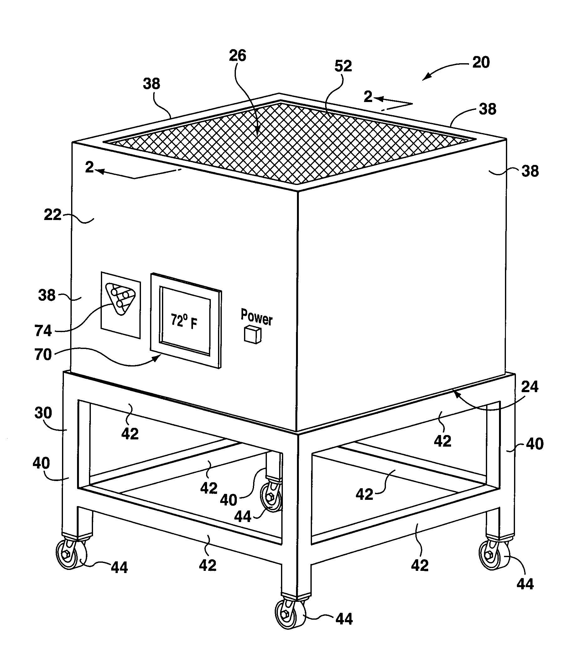
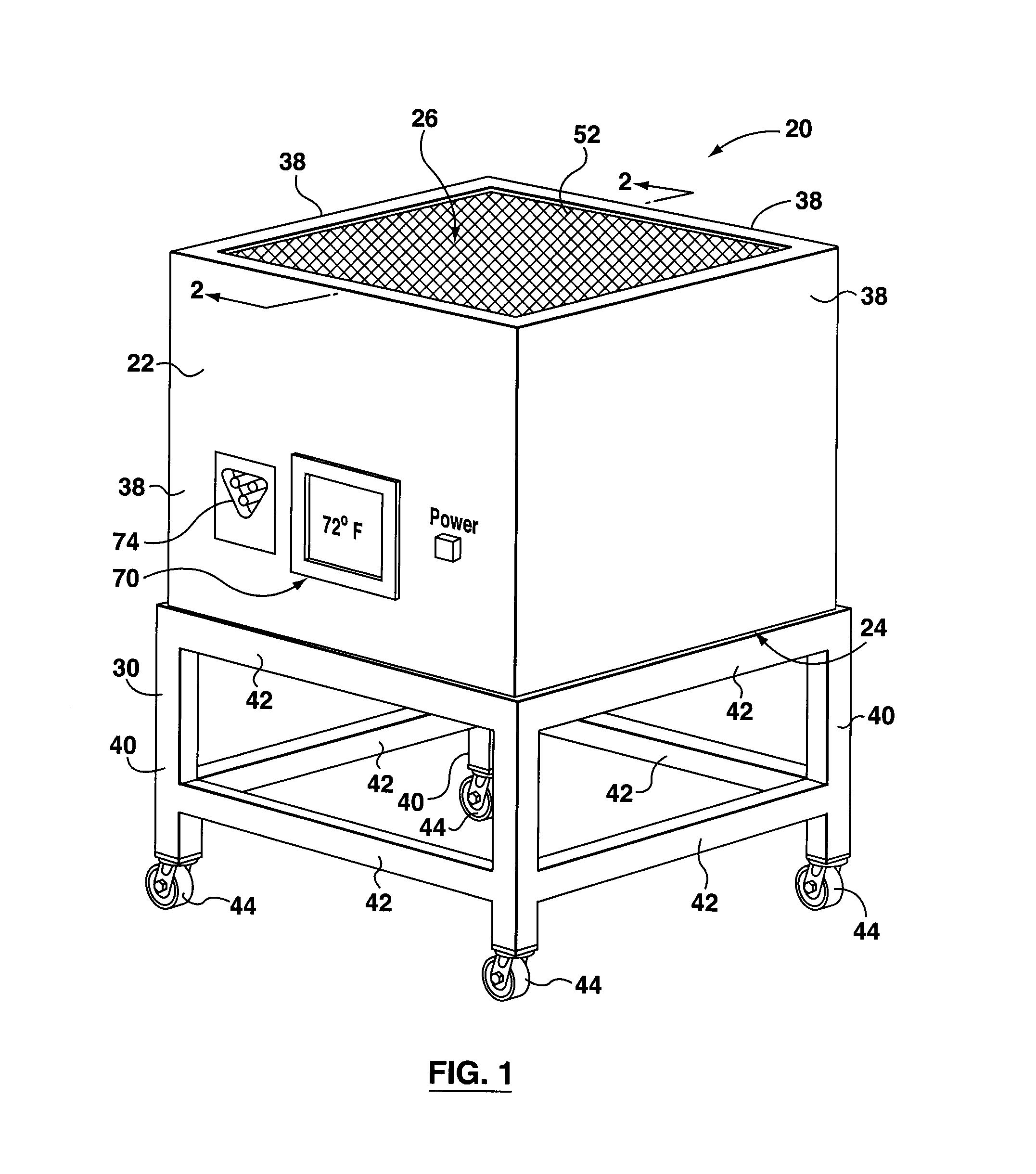
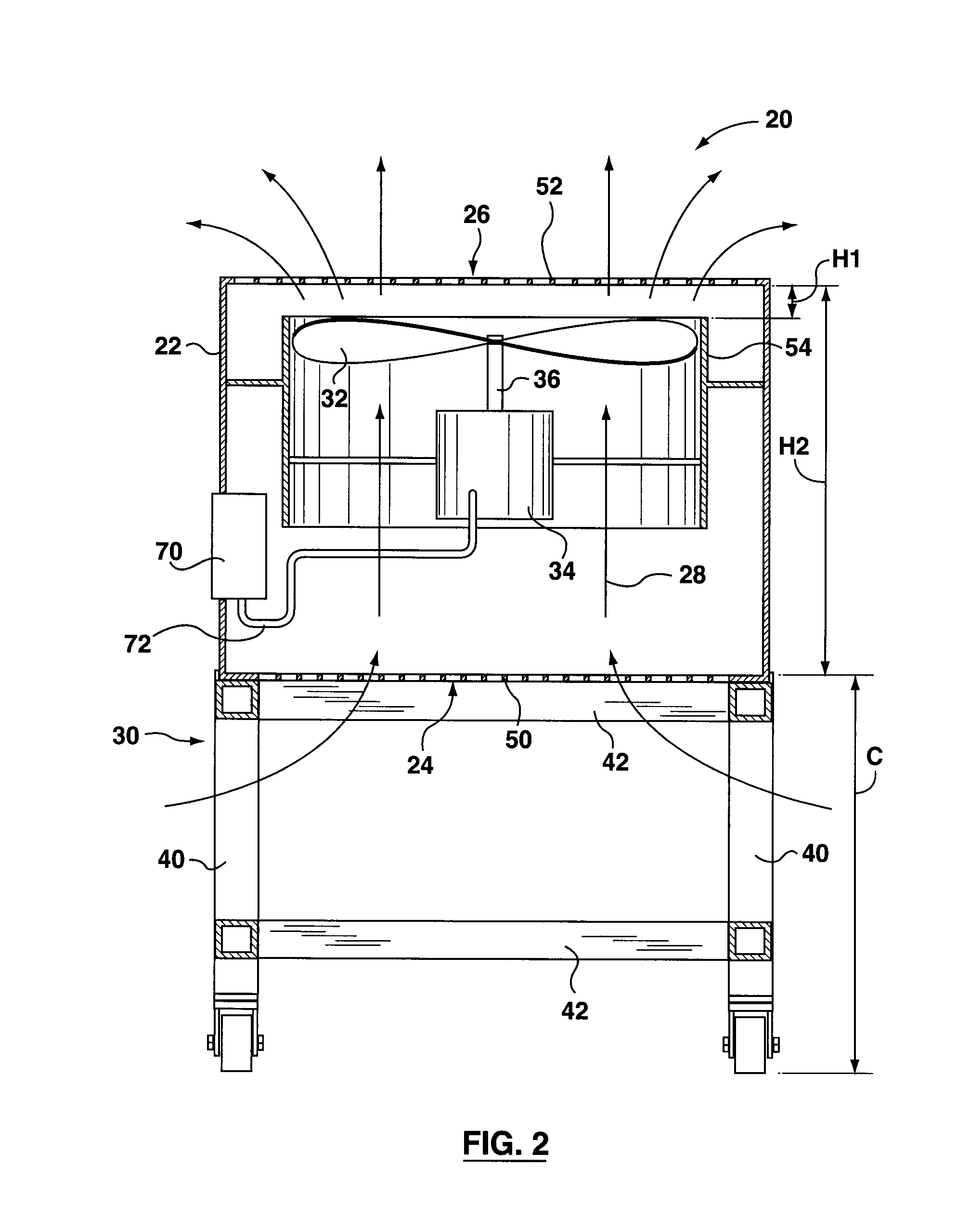
[0012]Some embodiments as described herein relate to systems and methods for controlling environmental parameters within an indoor environment using methods of forced mechanical convection to induce, amplify and / or manipulate the effects of natural convection phenomena, including at least one of the air de-lamination phenomena and the Coanda effect, to provide generally complete air distribution, circulation, de-stratification, and mixing of air within an indoor environment.
[0013]In some embodiments, some advantages provided by the systems and apparatus as described herein may include equalization of the temperature throughout an industrial or commercial environment (e.g. between the ceiling and ground level), elimination of hot and cold spots (e.g. for improving comfort), elimination of drafts from ceiling fans, improved air quality, reduction in energy consumption, and self-regulation.

Problems solved by technology

However, HVAC systems are often very inefficient and account for some of the highest energy costs in industrial and commercial environments.
New challenges are presented in addressing air movement in such large open spaced facilities.
In particular, conventional HVAC systems are generally poor at circulating air throughout these large open spaces.

Method used


Image

  • Ventilator system for recirculation of air and regulating indoor air temperature
  • Ventilator system for recirculation of air and regulating indoor air temperature
  • Ventilator system for recirculation of air and regulating indoor air temperature

Examples


Embodiment Construction

[0036]A number of factors and phenomena have been recognized herein as being worthy of consideration when designing apparatus and systems for circulating air.

[0037]One factor is de-lamination. De-lamination is a phenomenon whereby warm airflows and cool airflows tend to repel one another. For example, an upper layer of warm air will tend to float on top of a lower layer of cool air, generally without mixing between the layers. The upper and lower layers may be referred to as “stratified layers” having stratified layer “heights”. De-lamination is a result of different air temperatures, densities and turbulence intensity between cool and warm airflows, and generally results in energy waste and / or reduced efficiencies within an HVAC system.

[0038]It has been discovered that with higher velocity airflow, the temperature dependant de-lamination phenomenon begins to disappear, such that the heights of stratified layers tend to decrease.

[0039]For instance, in one example with stratified lay...


PUM


Abstract

An air circulator for amplifying and manipulating high volumes of low velocity air in order to circulate and regulate indoor air temperature within a commercial or an industrial environment. The air circulator includes a housing and a support member. The housing has an airflow passageway with a bottom end defining an air intake and a top end defining an air outlet. The air circulator further includes a fan positioned within the airflow passageway of the housing substantially adjacent to the top end of the housing. The support member supports the housing so as to dispose the air intake above the ground. The fan and the air outlet are configured to discharge air having a significant vertical component and a significant lateral component.

Description

RELATED APPLICATIONS[0001]This application claims the benefit of U.S. Provisional Patent Application Ser. No. 61 / 174,597 filed on May 1, 2009 and entitled “SYSTEM FOR REGULATING INDOOR AIR TEMPERATURE”, the entire contents of which are hereby incorporated by reference herein for all purposes.TECHNICAL FIELD[0002]The embodiments herein relate in general to apparatus and systems for air distribution and circulation, and in particular, to ductless apparatus and systems for circulating high volumes of low velocity air to regulate indoor air temperature.INTRODUCTION[0003]Heating, ventilation and air conditioning (HVAC) systems generally contribute to the comfort and satisfaction of workers, customers and tenants within indoor spaces by controlling and regulating air temperature. Properly tuned, HVAC systems can help improve employee productivity and contribute to good air quality. However, HVAC systems are often very inefficient and account for some of the highest energy costs in industr...

Claims


Application Information

Patent Timeline
Patent Type & Authority Applications(United States)
IPC IPC(8): F24F7/007
CPCF24F7/065F24F2221/125F24F11/30F24F2110/10F24F8/108F24F11/52F24F11/77F24F11/76F24F11/88F24F11/46F24F11/56Y02A50/20
Inventor CLAWSEY, MARK
Owner CLAWSEY MARK
Why Eureka
Try Eureka