Centrifugal switch bypass for reverse tumble dryers

a centrifugal switch and reverse tumble dryer technology, applied in drying machines, drying, light and heating equipment, etc., can solve the problems of long restart time for gas heating elements, short circuit breakage, and long restart time for heating elements

Active Publication Date: 2014-10-28
HAIER US APPLIANCE SOLUTIONS INC
View PDF39 Cites 2 Cited by
  • Summary
  • Abstract
  • Description
  • Claims
  • Application Information

AI Technical Summary

Problems solved by technology

Should the drum stop rotating or the rotation speed fall below the minimum rotation speed, the centrifugal switch returns to the normally open position, thereby breaking the circuit and cutting power to the heating element.
There is a long restart time for gas heating elements.
In other words, after power has been cut from the heating elements, there is a long delay in returning the heating element to the same heat output as before the power was cut.
For reversible dryers the long restart time presents a significant problem for dryers in which the drum shall change directions multiple times throughout a drying cycle.
The restart time can add significant time to the drying cycle.
For electric dryers the centrifugal switch typically carries higher current and reversible dryers would cause unnecessary activation and deactivation (i.e. “short cycling”) of the heating element.
This would in return reduce the useful life (i.e. reliability) of the centrifugal switch.
Simple removing or totally bypassing the centrifugal switch is not an option because removing or totally bypassing the centrifugal switch would remove an important safety feature that prevents runaway heating element conditions.
That is, removing the centrifugal switch may lead to the heating element being energized when the drum is stationary for extended periods of time.

Method used


Image

  • Centrifugal switch bypass for reverse tumble dryers
  • Centrifugal switch bypass for reverse tumble dryers
  • Centrifugal switch bypass for reverse tumble dryers

Examples


Embodiment Construction

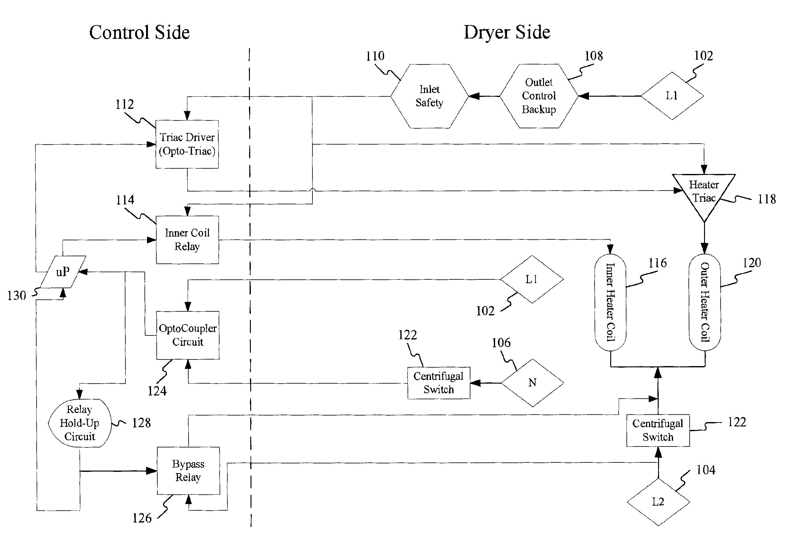
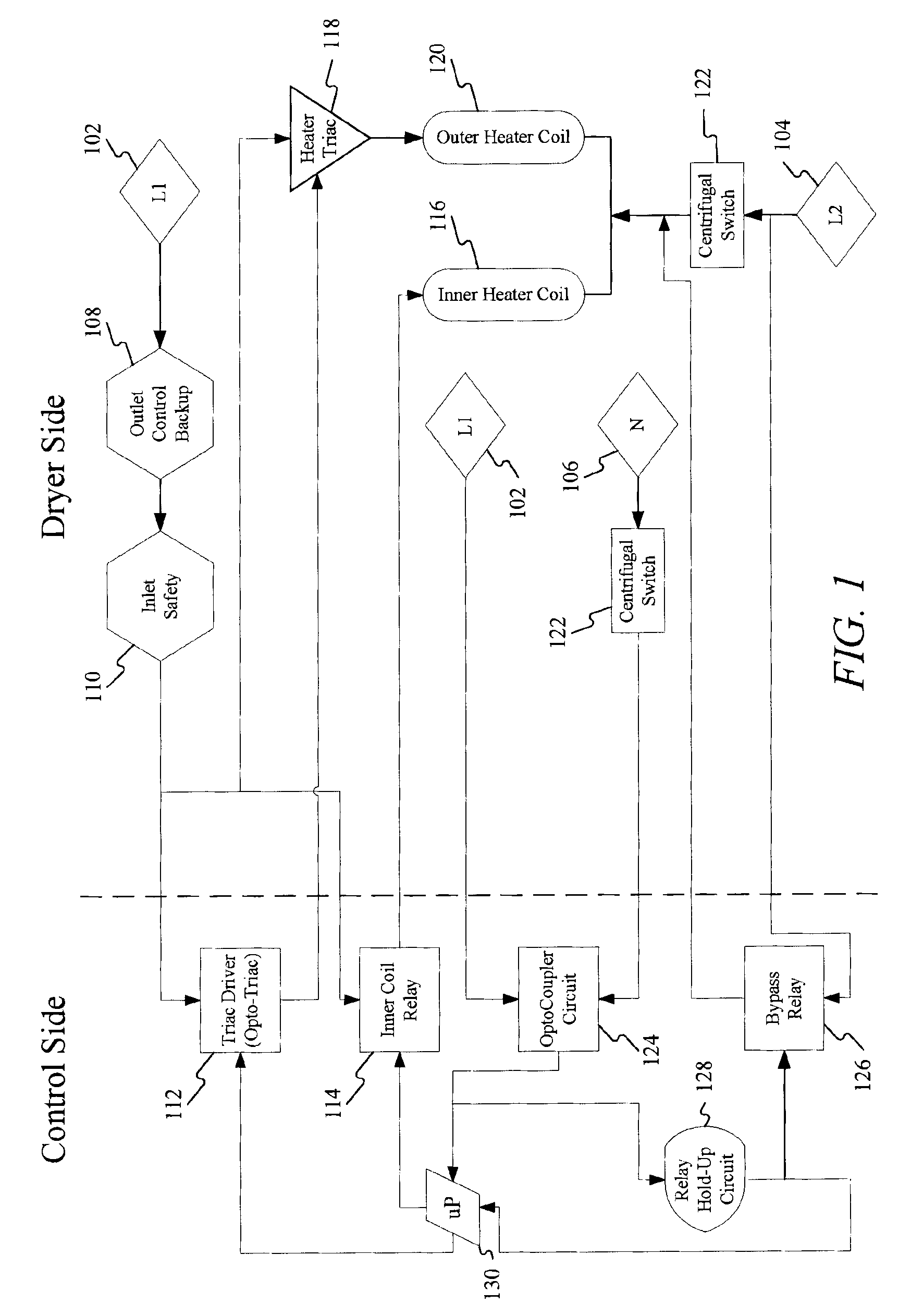
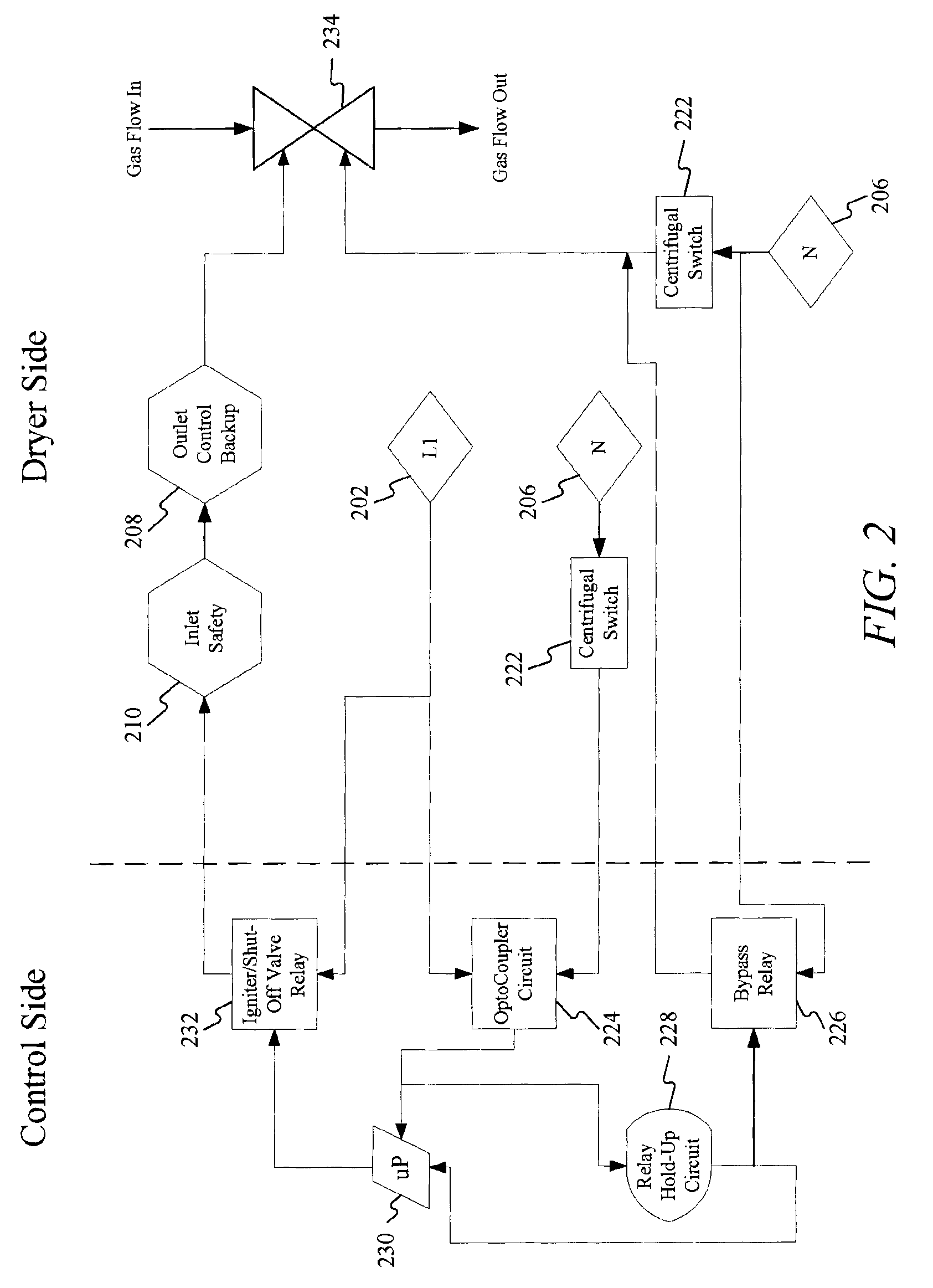
[0017]Various embodiments are described more fully below with reference to the accompanying drawings, which form a part hereof, and which show specific embodiments of the invention. However, embodiments may be implemented in many different forms and should not be construed as limited to the embodiments set forth herein; rather, these embodiments are provided so that this disclosure will be thorough and complete, and will fully convey the scope of the invention to those skilled in the art. Accordingly, the following detailed description is, therefore, not to be taken in a limiting sense.

[0018]Referring now to the figures, FIG. 1 depicts a control diagram for an electric dryer depicting a control side and a dryer side consistent with embodiments of the invention. Typically an electric dryer operates at 240 VAC with two hot wires (120 VAC each) as indicated by reference numerals 102 and 104 and one neutral wire, as indicated by reference numeral 106, powering the dryer. Upon entering t...


PUM


Abstract

Systems and methods for bypassing a centrifugal switch are disclosed. The systems may include a bypass relay operatively connected to the heating element and configured to bypass the centrifugal switch prior to the drum reversing rotational direction, and allow the heating element to remain energized during the drum reversing rotational direction. The centrifugal switch bypass circuit further includes a relay hold circuit operatively connected to the bypass relay and configured to cause the bypass relay to continue bypassing the centrifugal switch during the drum reversing rotational direction. The method may include, once the drum begins reversing the rotational direction, utilizing a bypass relay to bypassing the centrifugal switch. Finally, the method may include utilizing a relay hold circuit to cause the bypass relay to continue bypassing the centrifugal switch during reversal of the rotational direction.

Description

CROSS-REFERENCE TO RELATED APPLICATIONS[0001]The present application is related to U.S. patent application having Ser. No. 12 / 325,221 titled “Dryer With Reverse Tumble Action” filed Nov. 30, 2008 and U.S. patent application having Ser. No. 12 / 325,219titled “Dryer With Stationary Drying Cycle” filed Nov. 30, 2008.FIELD OF INVENTION[0002]Embodiments of the present invention relate to bypass switches. More specifically, embodiments of the present invention relate to systems and methods for bypassing centrifugal switches found in dryers.BACKGROUND OF THE INVENTION[0003]Centrifugal switches are a safety feature that prevents the heating element from operating when the drum is not rotating. Currently, dryers use centrifugal switches to ensure that the heating element does not operate when the drying compartment (i.e. drum) is not rotating. Generally, centrifugal switches used in dryers are normally open and as the drum reaches a minimum rotation speed, the switches are “thrown” to the clo...

Claims


Application Information

Patent Timeline
Patent Type & Authority Patents(United States)
IPC IPC(8): D06F58/28
CPCD06F2058/2854D06F2058/289D06F58/28D06F34/06D06F34/08D06F2103/00D06F2103/24D06F2103/38D06F2103/44D06F2105/28
Inventor RECIO, STEVEN M.GRAVEN, ERICKBURT, ASHLEYFRAZAR, JOSEPH
Owner HAIER US APPLIANCE SOLUTIONS INC
Why Eureka
Try Eureka