Display frame

a display frame and display technology, applied in the field of visual displays, can solve the problems of unnecessarily increasing the cost, unable to disclose the above-referenced patents, and the display of the above-referenced patents is relatively complex in its construction, so as to facilitate the display of artifacts and surrounding ornamental materials, simple manipulation and maintenance, and easy and inexpensive construction

Inactive Publication Date: 2014-11-04
LEBOFF LYNN ELIZABETH
View PDF14 Cites 4 Cited by
  • Summary
  • Abstract
  • Description
  • Claims
  • Application Information

AI Technical Summary

Benefits of technology

[0008]It is an object of this invention to provide an artifact display which is easy and inexpensive to construct and which permits the display of the artifact and surrounding ornamental material.
[0009]It is also an object of the invention to provide an artifact display which is very simple to manipulate and maintain.

Problems solved by technology

None of the above-referenced patents disclose, however, an artifact display which can be completely filed with ornamental material so as to completely surround the displayed artifact.
The displays of the above cited patents are relatively complex in their construction, adding unnecessarily to the cost thereof.
In addition, they also require the type of time-consuming effort to arrange the displayed material that often tends to cause the owner thereof to avoid maintaining or changing the ornamental material, which detracts from the utility of the display.

Method used


Image

  • Display frame
  • Display frame
  • Display frame

Examples


first embodiment

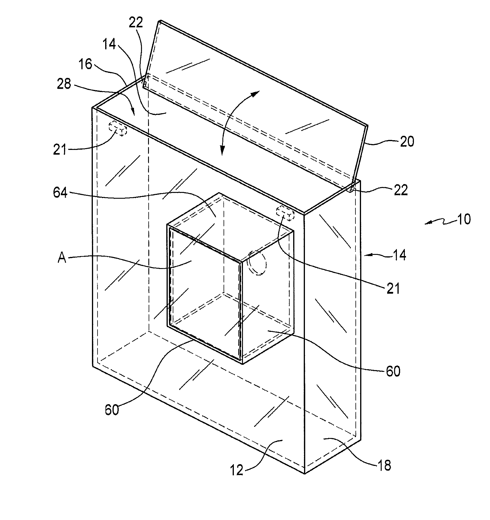
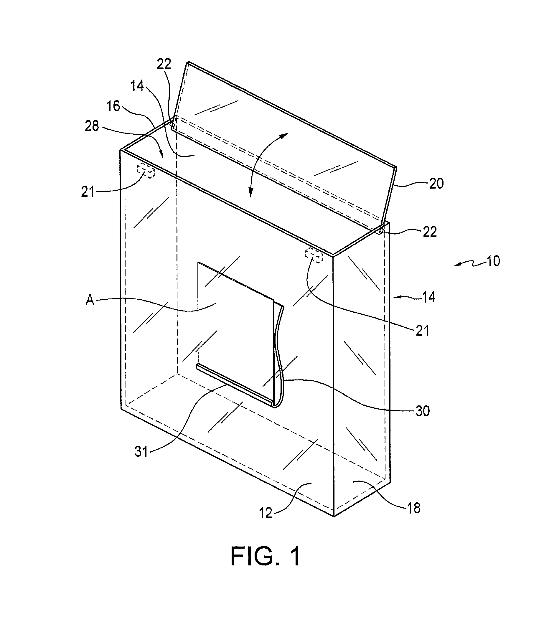
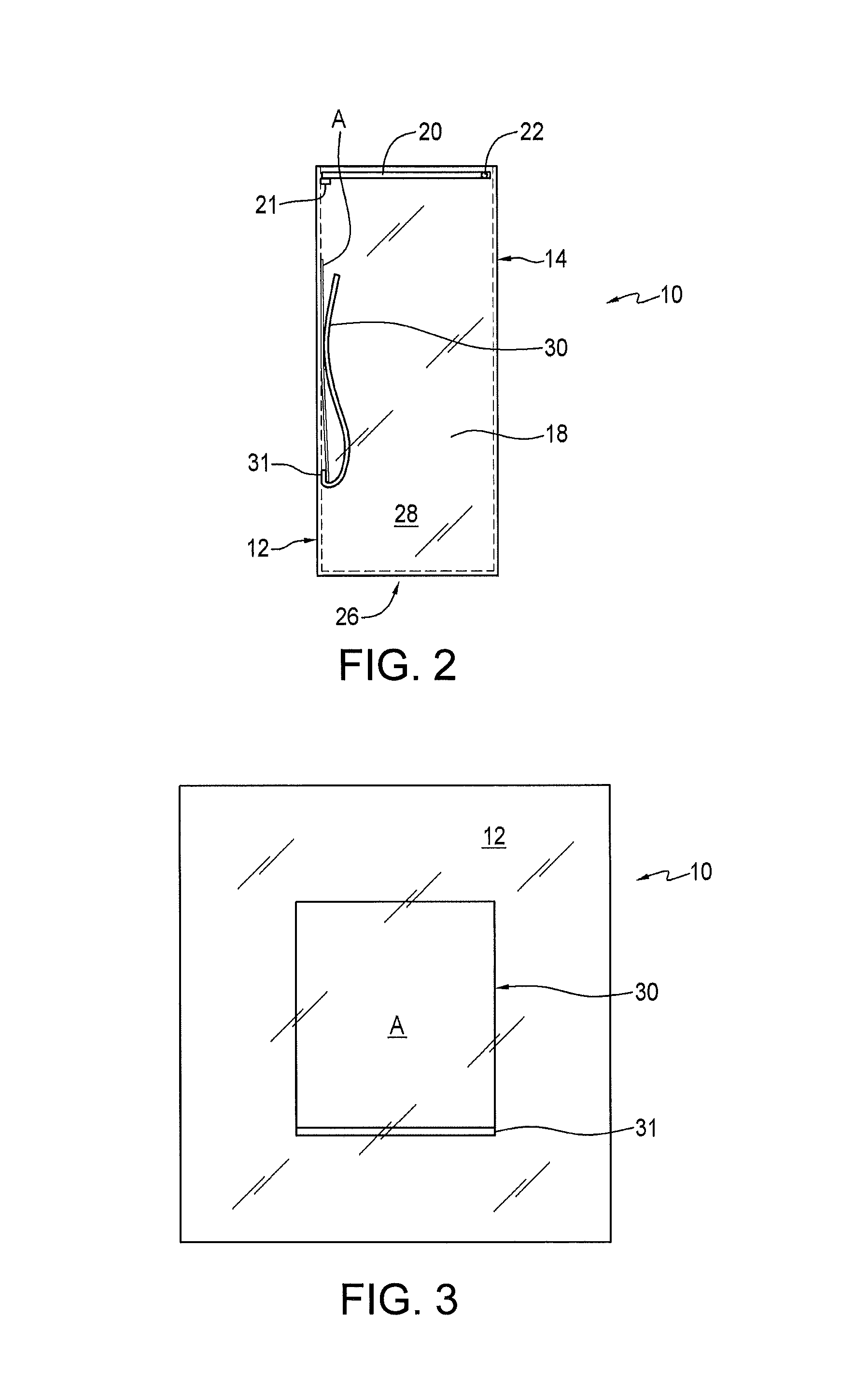
[0032]FIGS. 1 through 5 illustrate the invention, wherein an artifact display 10 is shown comprised of a rectangular container defined by front panel 12, rear panel 14, right and left side panels 16, 18, top panel 20 and bottom panel 26. Top panel 20 is optional. The foregoing panels comprise a container having an internal cavity or space. Top panel 20 may be hingedly connected to right and left side panels 16, 18, or front or rear panels 12, 14, in any manner, such as by the use of hinges 22. Stop members 21 may be employed to retain top panel in a closed position. Top panel 20 may be removably connected to display 10 in any other manner which will occur to those of skill in the art, an example of which is shown in FIGS. 17-19.

[0033]Front panel 12 is preferably manufactured of a clear material such as glass, Lexan®, Lucite® or any of the other polycarbonate resin thermoplastics or transparent thermoplastics such as acrylic glass, acrylic perspex or plexiglass, or any other transpar...

third embodiment

[0040]FIGS. 12-16 show the invention, wherein the artifact retention apparatus 30 is replaced by a retention sleeve defined by a rear retention panel 90 which is connected to the inner surface of front panel 12 along a connection seam 91 in a manner similar to that shown in connection with FIGS. 1-5. However, instead of a spring loaded clip 30, a fixed panel 90 is employed, which defines a space S between the inner surface of front panel 12 and retention panel 90 into which can be placed and removably stored an artifact. The distance between retention panel 90 and the inner surface of front panel 12 will depend upon the type of artifact to be displayed.

[0041]As stated previously, decorative material may be placed within cavity 28 after artifact A is inserted in sleeve S. Seam 91 may be colored so as to accentuate and / or outline the artifact.

[0042]It will be appreciated that, as top panel 20 may be associated with display 10 in any manner which will occur to those of skill in the art...


PUM


Abstract

An artifact frame comprised of a hollow container bordered on front, rear, left and right sides and bottom to define an interior cavity into which can be placed ornamental material. On the front or back panel, or side or bottom panels, the artifact to be displayed may be mounted. Any number of mounting configurations are contemplated to be within the scope of the invention. A top panel may also be provided, which may be partially or totally removable to permit access to the interior cavity for the mounting of the artifact and placement of the ornamental material.

Description

BACKGROUND OF THE INVENTION[0001]1. Field of the Invention[0002]This invention relates to visual displays, and, more particularly, relates to decorative frames for displaying artifacts such as photographs, artwork, etc., in which the display is constructed to accommodate decorative material to be associated with an ornament the display itself.[0003]2. Background Art[0004]Numerous displays have been proposed the purpose of which is to prominently display artifacts of significance such as photographs, artwork, collectibles, antiques, and the like. Typical displays comprise a frame having means associated therewith for displaying an artifact. The most commons such display is the well-known picture frame. modified forms of this basic display have also been proposed in a wide variety of configurations, some of which permit the placement of ornamental matter around the periphery of the display such as that shown in U.S. Pat. No. 83,797 to Schmitt, U.S. Pat. No. 5,174,054 to Politi, U.S. P...

Claims


Application Information

Patent Timeline
Patent Type & Authority Patents(United States)
IPC IPC(8): A47G1/06A47G1/12
CPCA47G1/0616A47G1/12Y10T428/13
Inventor LEBOFF, LYNN, ELIZABETH
Owner LEBOFF LYNN ELIZABETH
Why Eureka
Try Eureka