Pneumatic conveying process for particulate materials

a technology of pneumatic conveying and particulate materials, which is applied in the direction of gas current separation, liquid transfer devices, transportation and packaging, etc., can solve the problems of affecting the flow of materials, and even blocking the flow of materials through the pip

Active Publication Date: 2014-12-09
PELLETRON CORP
View PDF31 Cites 47 Cited by
  • Summary
  • Abstract
  • Description
  • Claims
  • Application Information

AI Technical Summary

Benefits of technology

[0017]It is another object of this invention to provide an effective conveying process for multiple types of plastic pellets from product bins to bulk silos for distribution to a production facility utilizing a common pipe.
[0028]These and other objects, features and advantages are accomplished according to the instant invention by providing a pneumatic conveying process that transports plastic pellets from a manufacturing source to a bulk silo for storage before being delivered to the ultimate production utilization of the plastic pellets. Multiple types or multiple sources of plastic pellets can be fed through a common pneumatic conveying pipe to respective bulk silos for temporary storage with diverter valves being utilized to direct product into and out of the common conveying pipe. Expanded elbow fittings are deployed at each directional change in the conveying lines to eliminate the creation of streamers at pipe bends. The plastic pellets are conveyed at a medium velocity between dense and dilute phases to provide a gentle conveying operation. A closed loop air supply system is used for dedusting devices providing a final removal of dust and debris from the stored product before being delivered to the ultimate utilization facility.

Problems solved by technology

In high velocity dilute phase systems in which the velocity is in the range of 25-40 meters / second, this friction results in the development of particle dust, broken particles, fluff, streamers (ribbon-like elements that can “grow” to become comparatively long and tangled), and glass fibers in glass filled products, that can impede the flow of materials or even totally block the flow of material through the pipe.
This results in high wall friction and friction between the pellets compressed in plugs moving through the pipe.
This high friction creates very fine, high electrostatic-charged dust within the product being conveyed.
In either case, using plastics as an example, such foreign debris would have a detrimental effect on the finished product.
Specifically, foreign debris, which by definition is different in composition from the primary material, and would include material such as dust, and non-uniform material of the primary product, such as streamers, would not necessarily have the same melting temperatures as the primary product being conveyed and would cause flaws when the plastics material is melted and molded.
These flaws result in finished products that are not uniform in color, may contain bubbles, and often appear to be blemished or stained, and are, therefore, unsalable.
It is important also to note that since these same non-uniform materials often do not melt at the same temperature as the primary product, the unmelted contaminants cause friction and premature wear to the molding machines, resulting in downtime, lost production, reduced productivity, increased maintenance and thus increased overall production costs.
Streamers can create problems throughout the conveying system, and in the manufacturing processes, but can also reduce or clog the discharge system to the scale, which results in errors in the weighing process.
Long streamers and fine micro dust are very difficult to remove from the product.
High air velocity and low product particle population is accomplished with low pressure resistance, but greatly increased damage to the product particles being conveyed.
Damage occurs in straight pipe sections, but is greatly increased whenever directional changes are imposed on the conveying system.
The dilute and dense phases of conveying have little flexibility in turn-down rations.
Reducing the flow rate in a dense phase conveying system will likely result in plugging the conveying pipes with particulate material.
Simply reducing the ration of product to air in a dilute phase conveying system can result in substantial damage to the product being conveyed.
In pneumatic conveying systems, whether the conveying system is operating under dilute phase or dense phase, the product particles suffer considerable damage during transport, particularly when changes in direction are being used.
Even with such elbow fittings, the combination of high velocity and centrifugal force does most of the damage to the particulate material, particularly with respect to heat sensitive plastic compounds.
Elbow fittings used in pneumatic conveying systems typically suffer wear at the elbow curve in line with the product flow into the elbow fitting, whether the elbow fitting is a short radius elbow or a long radius sweep elbow fitting.
The bouncing product particles create an area of turbulence that slows the speed of conveyance of the particles through the system.
Furthermore, the bouncing particles and the movement of the product particles around the outer surface of the elbow fitting generate friction, making the surface of the fitting warm to the touch.
This heat can have a detrimental effect on the product being conveyed, particularly when the product is heat sensitive, such as plastic pellets on which the edges of the pellets will melt and adhere to the pipe.

Method used


Image

  • Pneumatic conveying process for particulate materials
  • Pneumatic conveying process for particulate materials
  • Pneumatic conveying process for particulate materials

Examples


Embodiment Construction

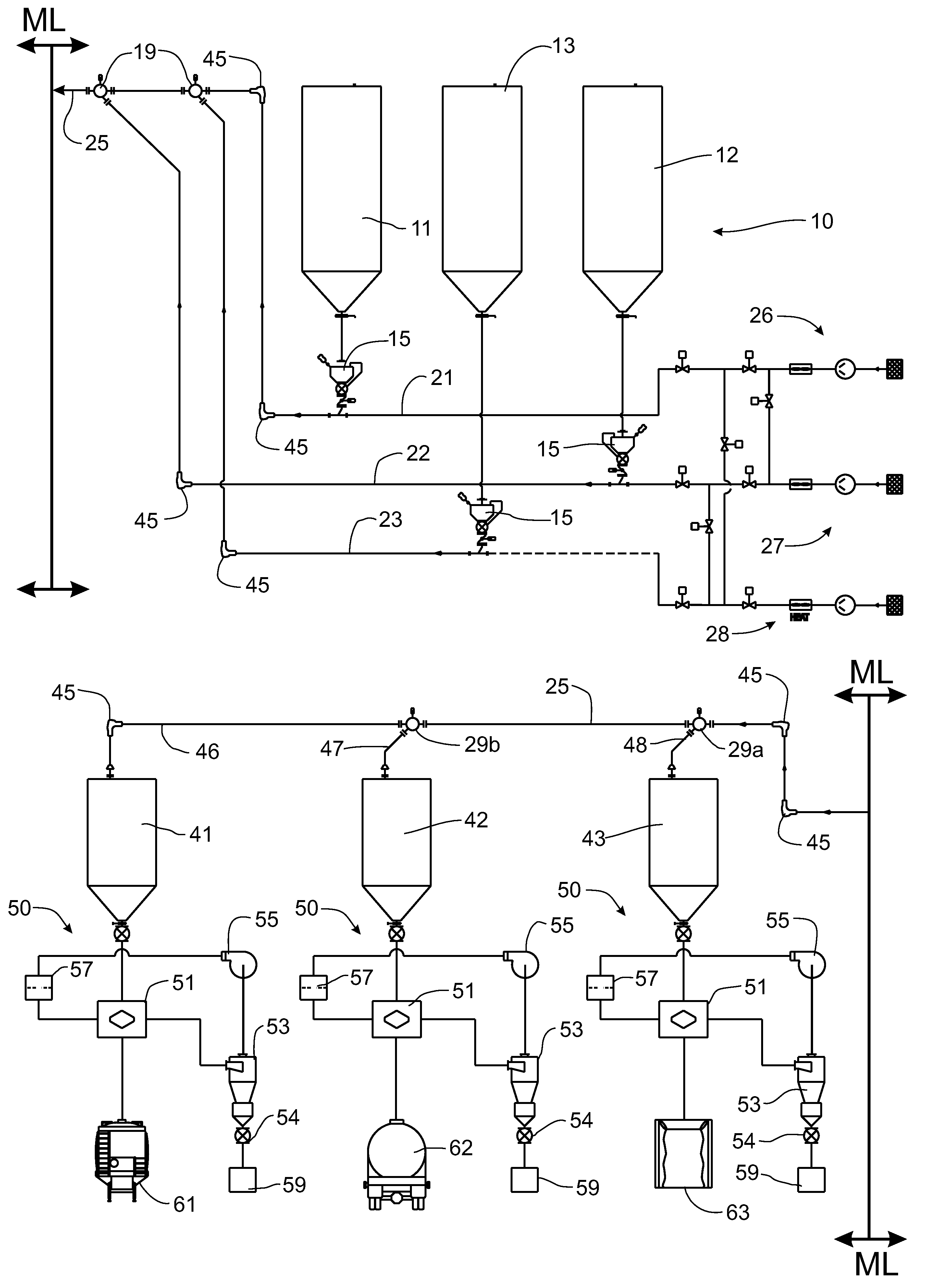
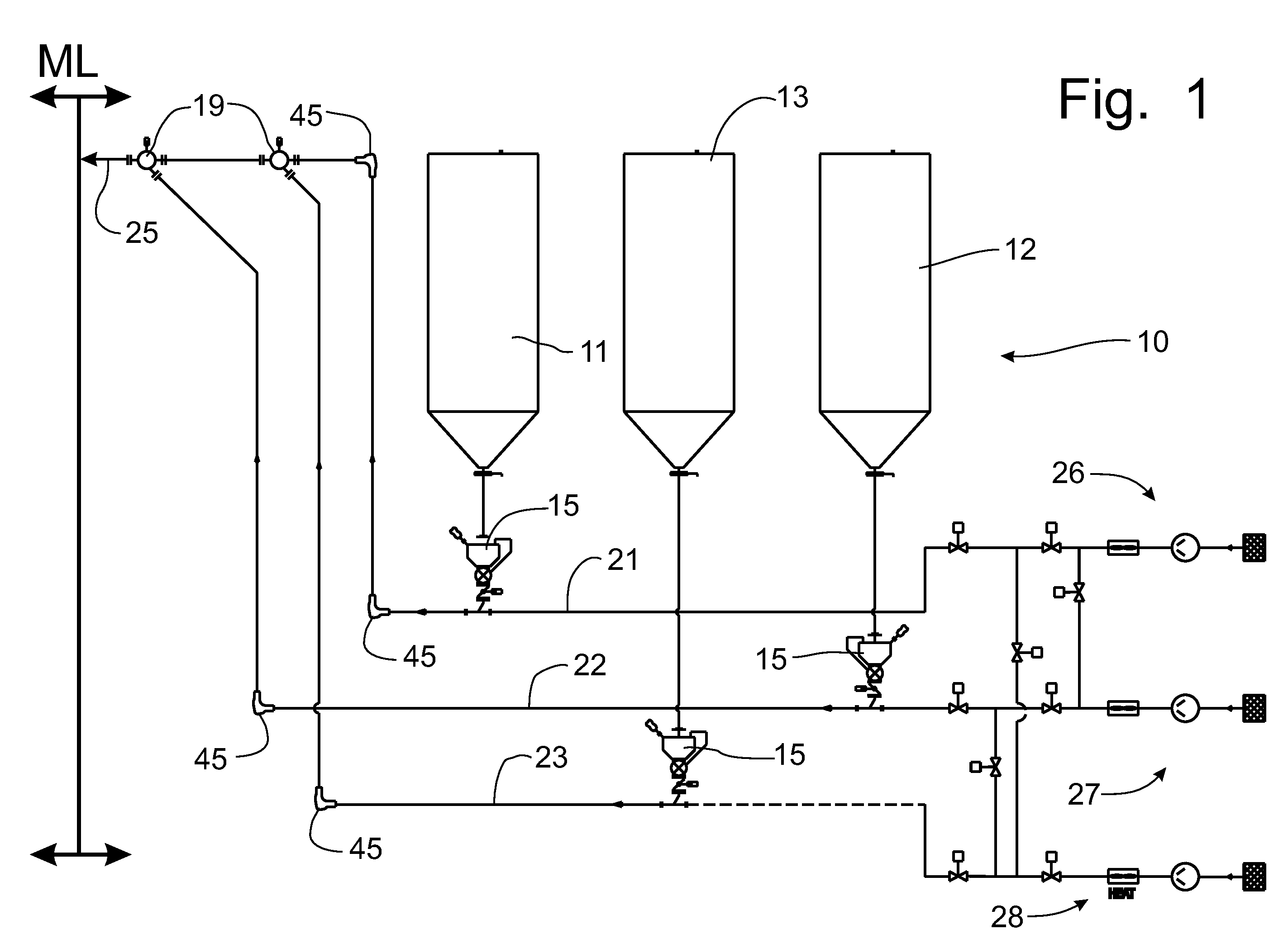
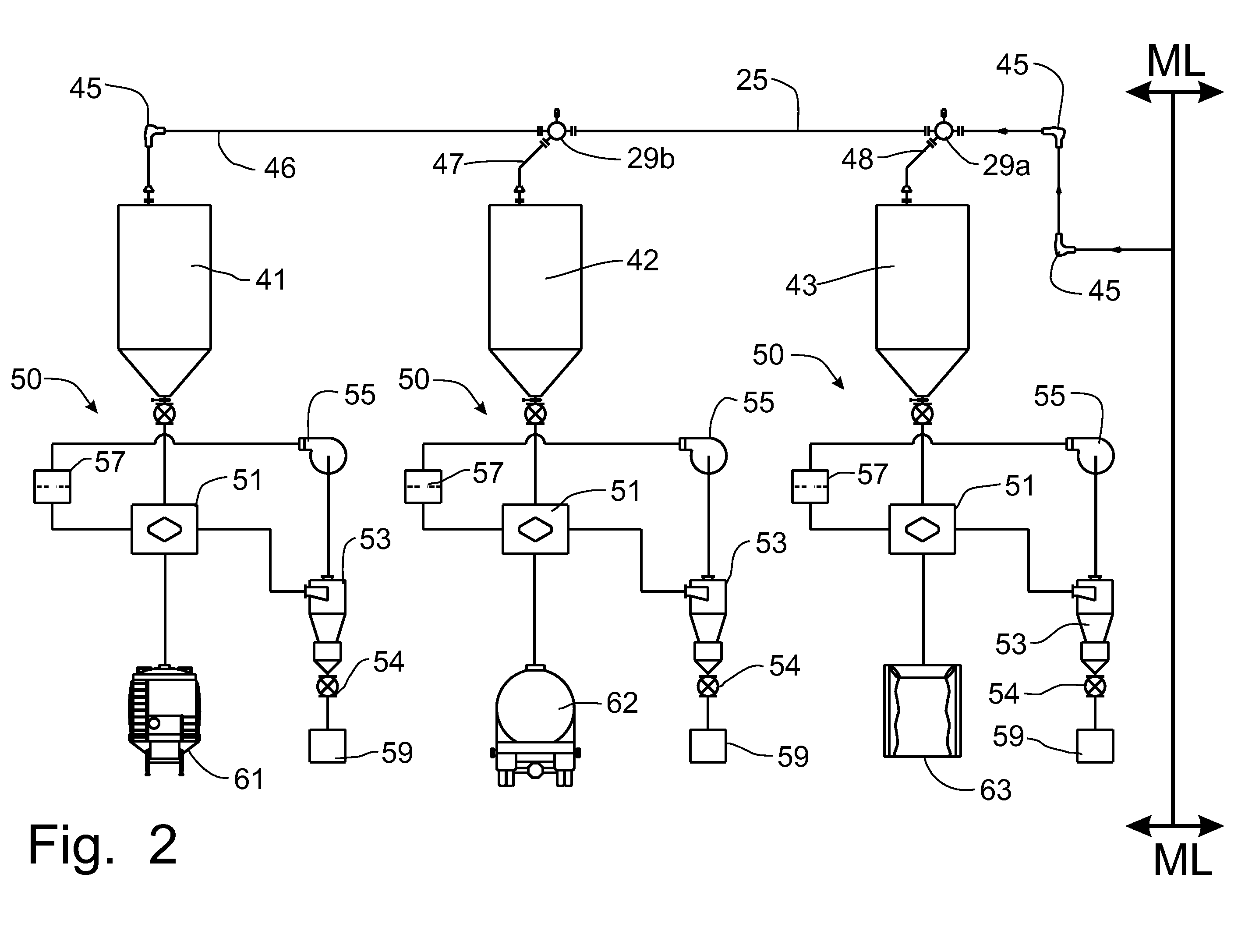
[0038]The expanded elbow fitting, rotary valve and dedusting apparatus are known in the art. A description of the structure and operation of an expanded elbow fitting can be found at U.S. Pat. No. 6,951,354, granted on Oct. 4, 2005, to Jerome I. Paulson, specifically as shown in FIGS. 1-4 and described at column 4, line 63, through column 7, line 54, and in U.S. Pat. No. 7,300,074, granted on Nov. 27, 2007, to Jerome I. Paulson, specifically as shown in FIGS. 1-5 and described at column 5, line 25, through column 6, line 54, both of which have been assigned to Pelletron Corporation. A description of the rotary valve configured to enhance conveying efficiencies and minimize air losses from the pneumatic conveying system can be found in U.S. patent application Ser. No. 12 / 717,152, filed on Mar. 4, 2010, specifically as shown in FIGS. 2-7 and described at Paragraphs [0033] through [0037]. A description of the structure and operation of a dedusting apparatus and a compact dedusting appa...


PUM


Abstract

A pneumatic conveying process transports plastic pellets from a manufacturing source to a bulk silo for storage before being delivered to the ultimate production utilization of the plastic pellets. Multiple types or multiple sources of plastic pellets can be fed through a common pneumatic conveying conduit to respective bulk silos for temporary storage with diverter valves being utilized to direct product into and out of the common conveying conduit. Expanded elbow fittings are deployed at each directional change in the conveying lines to eliminate the creation of streamers at conduit bends. The plastic pellets are conveyed at a medium velocity between dense and dilute phases to provide a gentle conveying operation. A closed loop air supply system is used for dedusting devices providing a final removal of dust and debris from the stored product before being delivered to the ultimate utilization facility.

Description

CROSS-REFERENCE TO RELATED APPLICATIONS[0001]This application claims domestic priority on U.S. Provisional Patent Application Ser. No. 61 / 367,768, filed on Jul. 26, 2010, the content thereof being incorporated herein by reference.FIELD OF THE INVENTION[0002]The invention disclosed in this application is directed generally to a process for conveying particulate materials, such as plastic pellets and other granular bulk solids with similar product properties, and particularly to the a pneumatic conveying process, consisting of a combination of technologies, that provides a high quality particulate material for the end user of the particulate material with a minimum of dust, streamer and other imperfection-causing debris within the particulate material.BACKGROUND OF THE INVENTION[0003]It is well known, particularly in the field of transporting and using particulate materials, commonly powders, granules, pellets, and the like that it is important to keep product particles as free as pos...

Claims


Application Information

Patent Timeline
Patent Type & Authority Patents(United States)
IPC IPC(8): B65G53/60B65G53/36B65G53/06
CPCB65G53/06B65G53/36B65G53/60B65G53/04B65G53/34B65G53/52B65G2201/042B65G2812/1608
Inventor SCHNEIDER, HEINZWAGNER, PAUL
Owner PELLETRON CORP
Why Eureka
Try Eureka