Configuring synchronous optical switches

a technology of optical switches and synchronous switches, applied in data switching networks, multiplex communication, wavelength-division multiplex systems, etc., can solve the problem that high-performance scheduling algorithms cannot be used, and achieve the effect of improving the router

Active Publication Date: 2015-01-06
TELEFON AB LM ERICSSON (PUBL)
View PDF14 Cites 0 Cited by
  • Summary
  • Abstract
  • Description
  • Claims
  • Application Information

AI Technical Summary

Benefits of technology

[0005]It is an object to provide an improved method of configuring a synchronous optical packet switch and to provide an improved router.
[0011]The method provides for efficient data routing across a synchronous optical switch. The method allows for switch scalability in terms of the number of optical switch transmitter modules and optical switch receiver modules comprising the synchronous optical switch. The method may be used to configure a synchronous optical switch comprising a plurality of transmitter / receiver cards. The method may be used to configure multi-card modular wavelength division multiplexed (WDM) optical packet switches. In the method, steps a. and c. can be specified to meet desired complexity and performance requirements.

Problems solved by technology

The method can therefore be used in connection with large switches which many known, high-performance scheduling algorithms cannot be used with, since the known algorithms cannot perform the scheduling within the tight time constraints required by such switches.

Method used


Image

  • Configuring synchronous optical switches
  • Configuring synchronous optical switches
  • Configuring synchronous optical switches

Examples


first embodiment

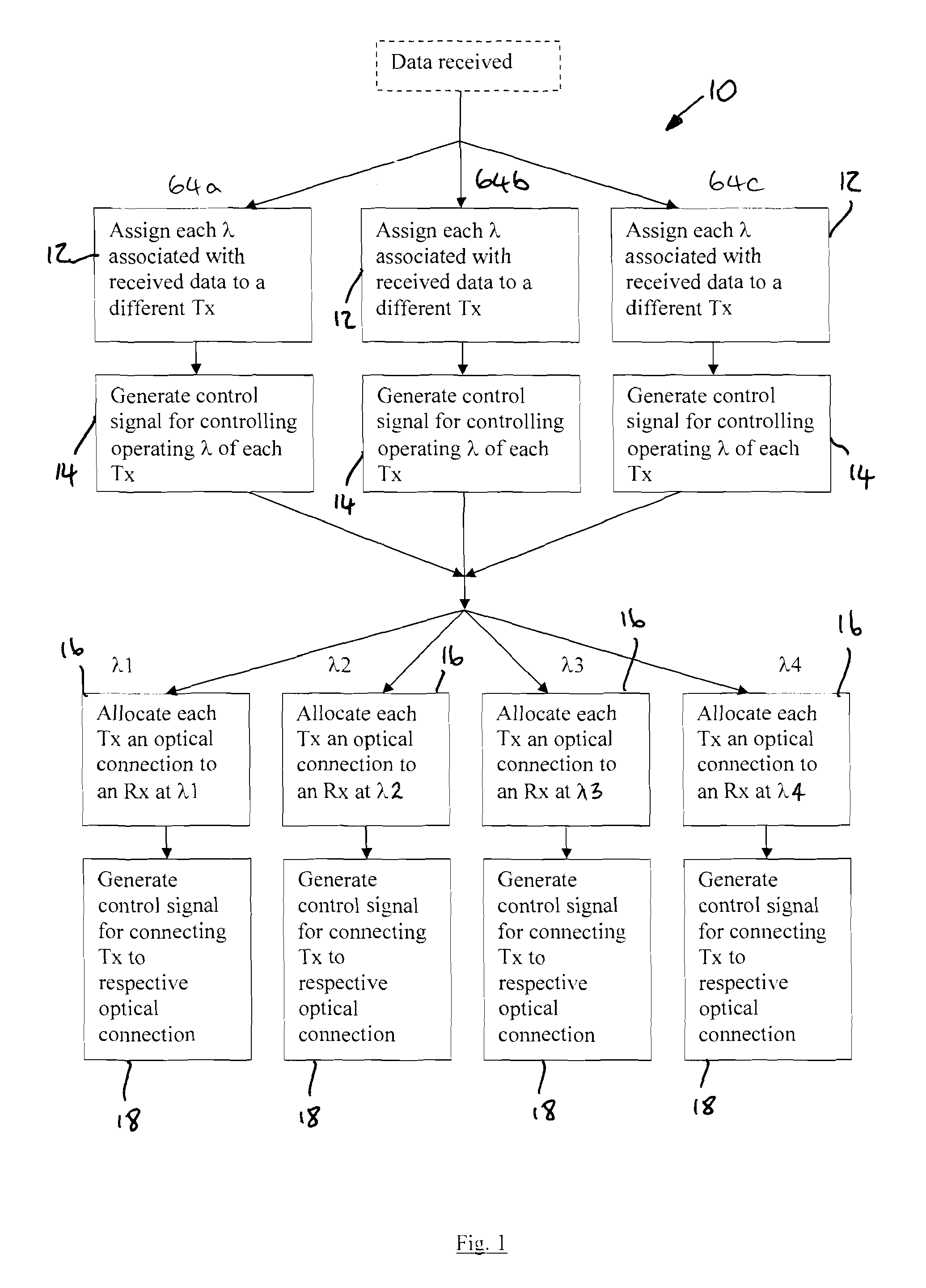
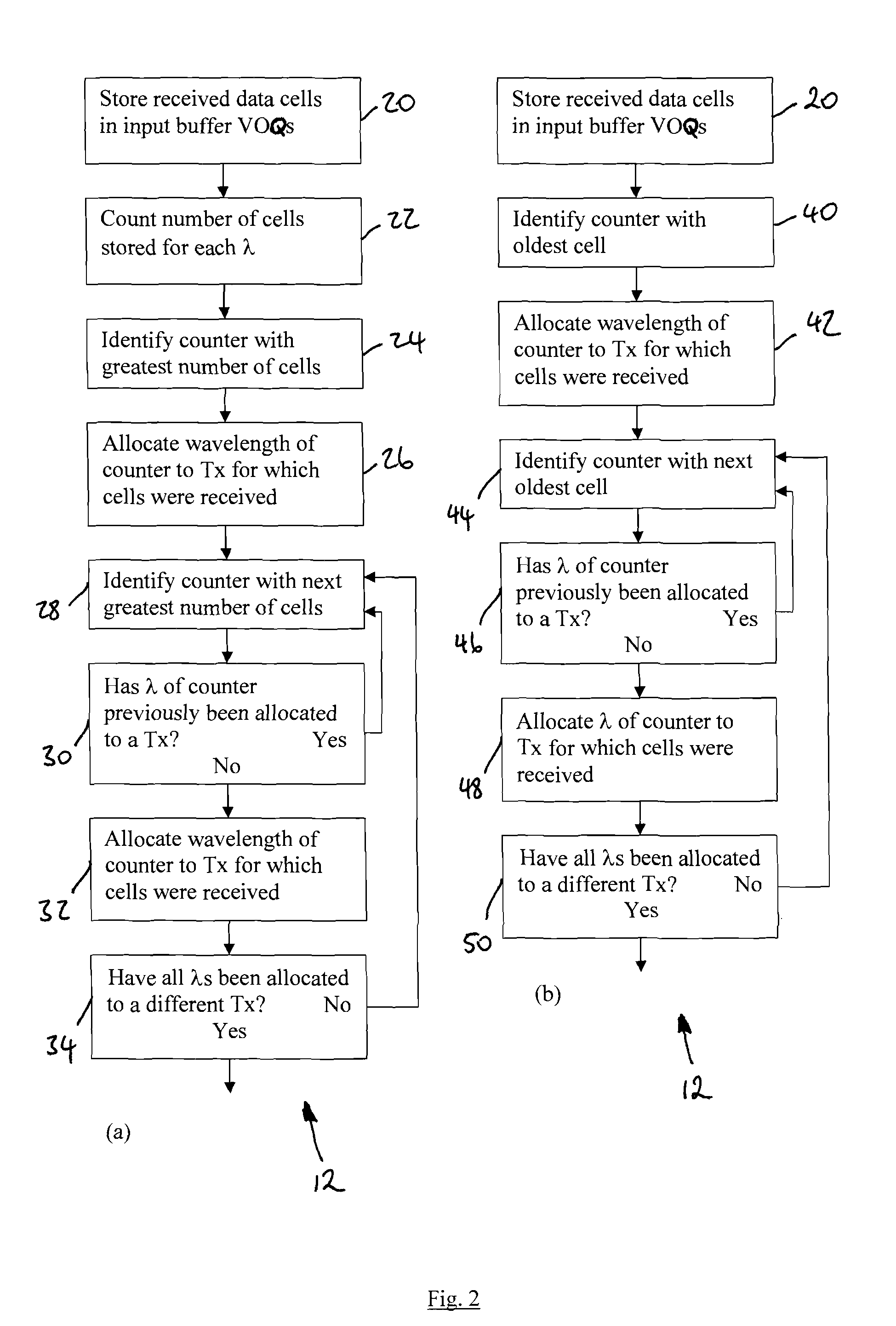
[0046]Referring to FIGS. 1 to 7, the invention provides a method 10 of configuring a synchronous optical switch 60.

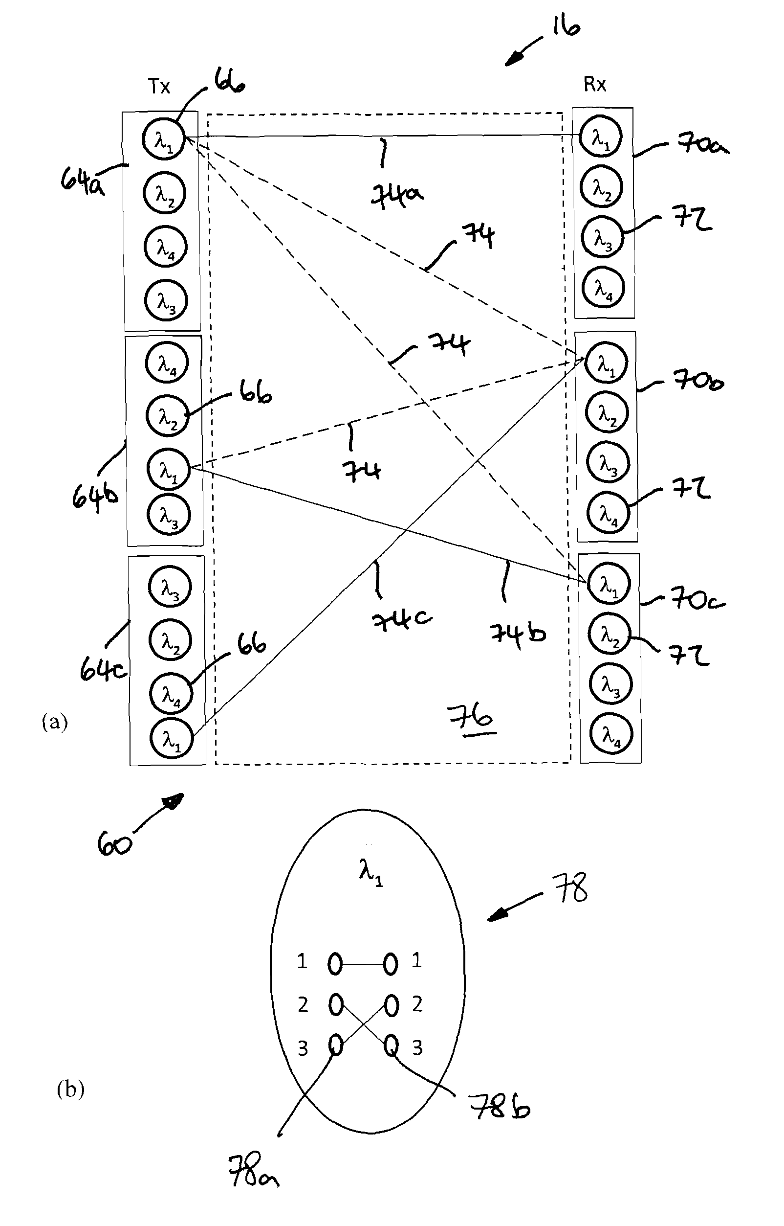
[0047]A synchronous optical switch 60 suitable for being configured according to the method 10 is shown in part in FIGS. 3 and 7 and comprises a first plurality (three in this example) of optical switch transmitter modules 64a, 64b, 64c and a corresponding plurality (three) of optical switch receiver modules 70. Each transmitter module 64a, 64b, 64c comprises a second plurality (four in this example) of tunable optical transmitters 66. Each receiver module 70 comprises a corresponding plurality (four) of fixed optical receivers 72. The tunable optical transmitters 66 and optical receivers 72 are connected via an optical backplane 76 comprising a third plurality of optical connections 74. The number of optical connections 74 is equal to the number of transmitter modules 64a, 64b, 64c (C) multiplied by the number of tunable optical transmitters 66 (L), and in this example...

second embodiment

[0067]Referring to FIG. 8, the invention provides a router 80 comprising a synchronous optical switch 60. The synchronous optical switch 60 is of the same type as shown in FIGS. 3 and 7, but is here shown in more detail.

[0068]The synchronous optical switch 60 comprises a switch control unit 82, three optical switch transmitter modules 64a, 64b, 64c, three optical switch receiver modules 70, and an optical backplane 76 providing twelve optical connections (not shown in FIG. 8).

[0069]Each transmitter module 64a, 64b, 64c comprises four tunable optical transmitters 66 and a transmitter module control unit 68. Each optical switch receiver module 70 comprises four optical receivers.

[0070]Each transmitter module control unit 68 is arranged to assign wavelengths associated with received data cells to the tunable optical transmitters within its respective transmitter module 64a, 64b, 64c, according to the method 10 as described above. Each transmitter module control unit 68 is further opera...


PUM


Abstract

A method (10) of configuring a synchronous optical switch to route received data cells. The synchronous optical switch comprises optical switch transmitter modules, each comprising tunable optical transmitters, optical switch receiver modules, each comprising optical receivers, and optical connections between the transmitter modules and receiver modules. For each optical switch transmitter module, the method: assigns (12) wavelengths associated with the received data cells to the transmitters such that each wavelength is assigned to a different transmitter; and generates (14) a control signal for controlling the operating wavelength of each transmitter. For each wavelength, the method: allocates (16) to each transmitter an optical connection such that each optical switch transmitter module has no more than one connection exiting it at said wavelength and each optical receiver module has no more than one connection entering it at said wavelength; and generates (18) a control signal for connecting each transmitter to the respective optical connection.

Description

[0001]This application is the U.S. national phase of International Application No. PCT / EP2008 / 068148, filed 22 Dec. 2008, which designated the U.S., the entire content of which is hereby incorporated by reference.FIELD OF THE INVENTION[0002]The invention relates to a method of configuring a synchronous optical switch and to a router comprising a synchronous optical switch.BACKGROUND OF THE INVENTION[0003]The amount and data rate of traffic transmitted across optical communications networks continues to increase and network routers will therefore be required to route data at faster and faster rates, likely at data throughput rates in the range of tens or hundreds of Terabits per second (Tb / s). Electronic interconnection networks currently used within routers are approaching their fundamental operational limitations, particularly in terms of their power density.[0004]Optical packet switches have been proposed as a solution for geographic area networks, where optical packets are transp...

Claims


Application Information

Patent Timeline
Patent Type & Authority Patents(United States)
IPC IPC(8): H04L12/66H04J14/02H04Q11/00
CPCH04J14/0227H04Q11/0005H04L49/3045H04L49/357H04Q2011/0018H04Q2011/0039H04Q2011/005
Inventor ANDRIOLLI, NICOLABIANCHI, ALBERTOCASTOLDI, PIERORAPONI, PIER GIORGIO
Owner TELEFON AB LM ERICSSON (PUBL)
Why Eureka
Try Eureka