
Combined probe head for a vertical probe card and method for assembling and aligning the combined probe head thereof
a combined probe and probe head technology, applied in the field of combined probe heads, can solve the problems of increasing repair costs, easy wear and abrasion of the probe head b>4/b>, and the inability to accurately align the sub-probe head, so as to avoid mutual interference and ensure the alignment of the sub-probe head. the effect of accuracy
- Summary
- Abstract
- Description
- Claims
- Application Information
AI Technical Summary
Benefits of technology
Problems solved by technology
Method used
Image

Examples
embodiment 1
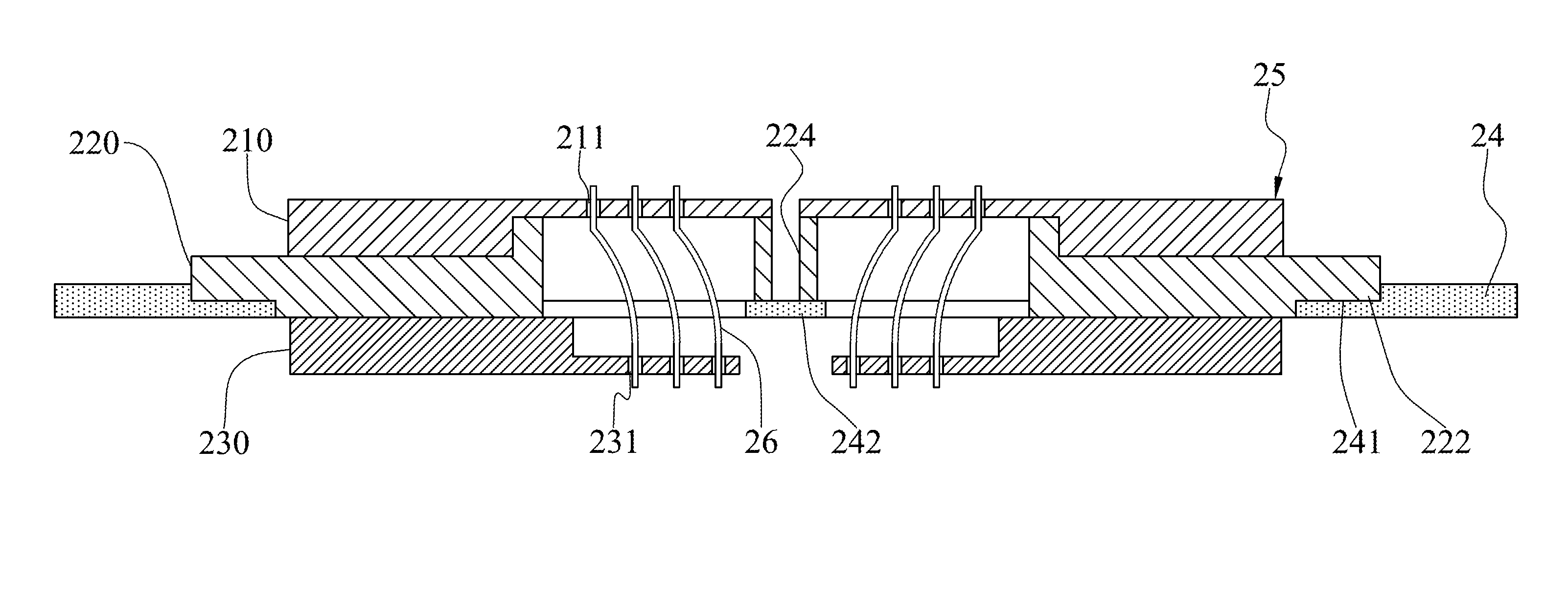
[0022]In this embodiment, a combined probe head 20 having three dies is provided. Please refer to FIG. 2-1. As shown, the combined probe head 20 may include an upper die (UD) 21, a middle die (MD) 22, a lower die (LD) 23, and a locating plate 24. The upper die 21, the middle die 22, and the lower die 23 include a plurality of upper sub-dies 210, a plurality of middle sub-dies 220, and a plurality of lower sub-dies 230, respectively. Be noted that a total number of the upper sub-dies 210 of the upper die 21, a total number of the middle sub-dies 220 of the middle die 22, and a total number of the lower sub-dies 230 of the lower die 23 are equal to each other, and the positions of the upper sub-dies 210, the middle sub-dies 220, and the lower sub-dies 230 are configured up and down respectively corresponding to each other. However, the total number of the upper sub-dies 210, the middle sub-dies 220, and the lower sub-dies 230 are not limited to any particular number, which is to be co...
embodiment 2
[0027]In Embodiment 2, a combined probe head 30 having two dies is provided. FIG. 4-1 is a 3D exploded view of the combined probe head 30 and FIG. 4-2 is an assembly cross-sectional view of the combined probe head 30. This embodiment can be applied to a vertical probe card with multi-DUT. The combined probe head 30 may include an upper die 31, a lower die 32, and a locating plate 33. The upper die 31 and the lower die 32 include a plurality of upper sub-dies 310 and a plurality of lower sub-dies 320, respectively. Be noted that a total number of the upper sub-dies 310 of the upper die 31 and a total number of the lower sub-dies 320 of the lower die 32 are equal to each other (as shown in FIG. 4-1, the total number is equal to two), and the positions of the upper sub-dies 310 and the lower sub-dies 320 are arranged up and down corresponding to each other. Besides, there are a plurality of corresponding holes 311, 321 disposed on the upper sub-dies 310 and the lower sub-dies 320, resp...
embodiment 3
[0033]In the Embodiment 3, another combined probe head 40 is provided, which can be applied to a vertical probe card with high pin count and / or multi-DUT. Please refer to the assembly structural view shown in FIG. 5-1. The combined probe head 40 may include an upper die 41, a lower die 42, and a locating plate 43. The upper die 41 includes a plurality of upper sub-dies 410 (such as, the three upper-sub-dies 410 shown in FIG. 5-1), wherein the upper sub-dies 410 are in horizontal alignment with each other, and there are a plurality of holes 411 disposed on each of the upper sub-dies 410. The lower die 42 includes a plurality of layout areas 420 of the probes, wherein there is a plurality of holes 421 disposed on each of the layout areas 420. Therefore, each upper sub-die 410 can correspond to one of the layout areas 420 to be disposed on the lower die 42, such that a plurality of probes 44 can be inserted between the upper sub-dies 410 and the layout areas 420 of the lower die 42. Th...
PUM
 Abstract
Description
Claims
Application Information