Engine control system for actuator control

a technology of actuator control and control system, which is applied in the direction of electric control, machines/engines, instruments, etc., can solve the problems of parameter deviation, interference between the different types of performance parameters, and the increase of smoke emitted from the engine, so as to eliminate mutual interference

Active Publication Date: 2012-09-20
DENSO CORP
View PDF7 Cites 4 Cited by
  • Summary
  • Abstract
  • Description
  • Claims
  • Application Information

AI Technical Summary

Benefits of technology

[0013]The third correlation data, as described above, represents the correlations between the different types of combustion parameters and the different types of controlled parameters. In other words, the third correlation data does not define one-to-one correspondences between the combustion parameters and the controlled parameters, but defines the plurality of correlations between each of the combustion parameters and the controlled parameters, thereby eliminating mutual interferences among the combustion parameters contributing to the deterioration of control of the engine.

Problems solved by technology

The decreasing of an interval (i.e., one of combustion parameters) between the pilot injection events to reduce the combustion noise (i.e., one of the performance parameters) may, therefore, result in an increase in amount of smoke (i.e., one of the performance parameters) emitted from the engine.
Specifically, when the engine control system calculates target values of the performance parameters independently of each other and changes a plurality of controlled variables or parameters for actuators simultaneously for bringing them into agreement with the target values, it may result in interference between the different types of the performance parameters in that when one of the performance parameters reaches its target value, another performance parameter deviates from its target value.
In other words, a mutual interference between the performance parameters may make it impossible to control the performance parameters separately.

Method used


Image

  • Engine control system for actuator control
  • Engine control system for actuator control
  • Engine control system for actuator control

Examples


first embodiment

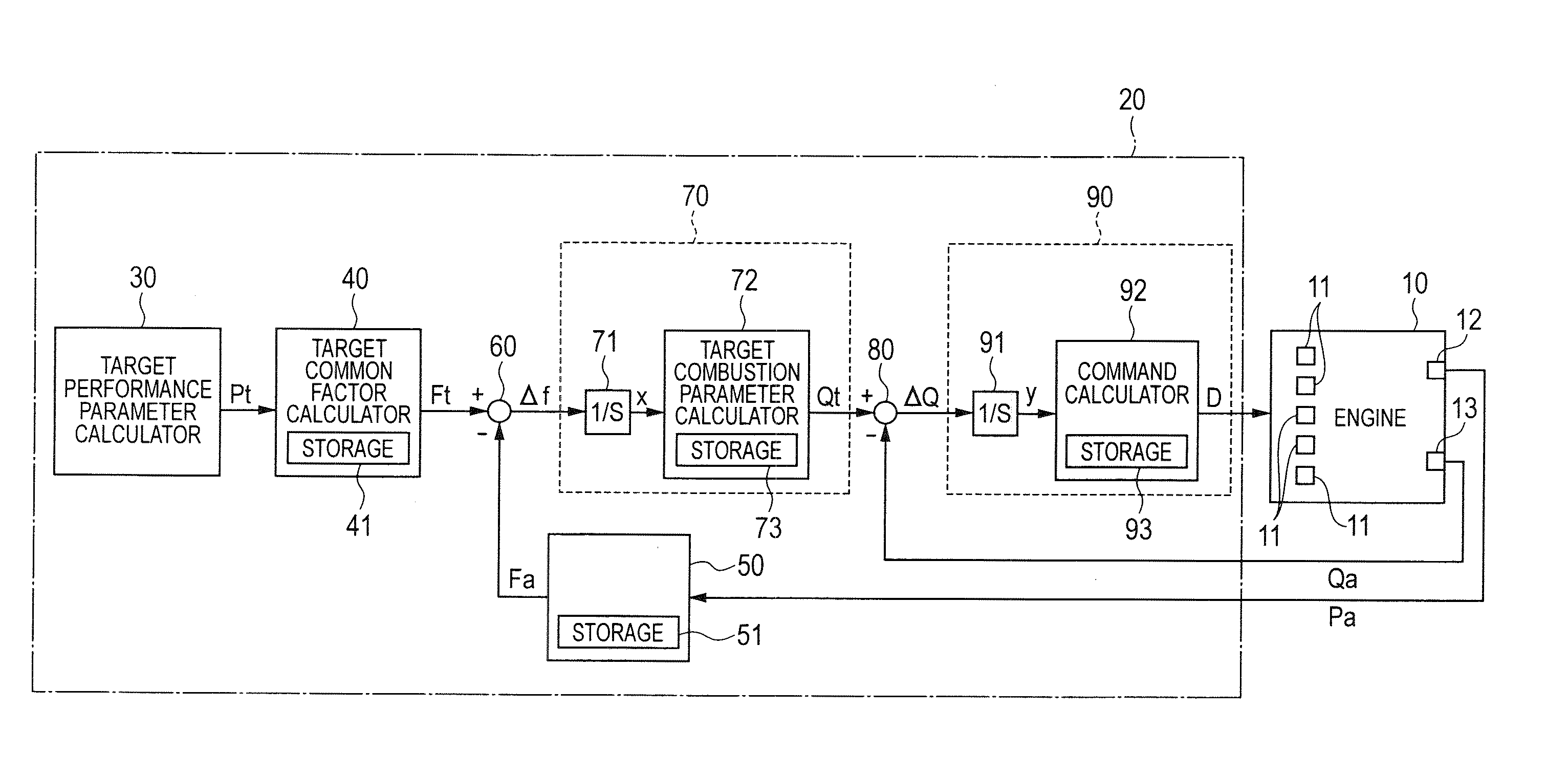
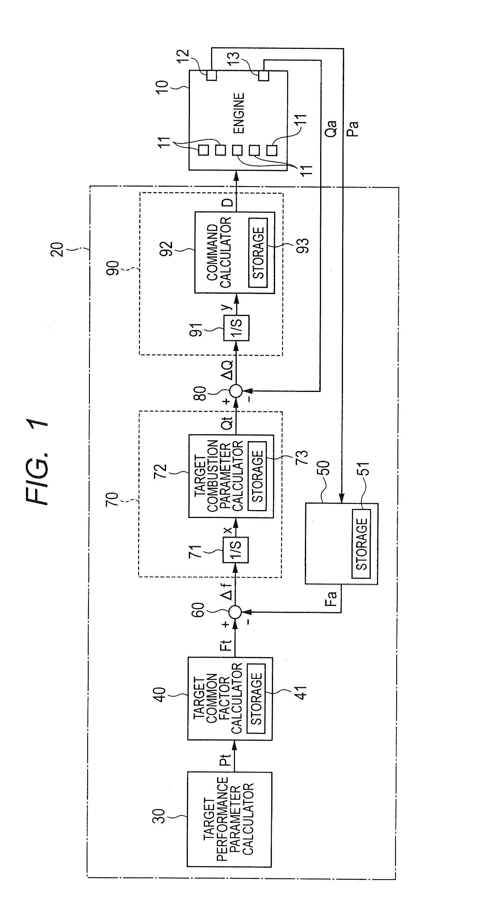
[0024]Referring to the drawings, wherein like reference numbers refer to like parts in several views, particularly to FIG. 1, there is shown an engine control system which is designed to control an operation of an internal combustion engine 10 for automotive vehicles. The following discussion will refer to, as an example, a self-ignition diesel engine in which fuel is sprayed into cylinders at a high pressure.

[0025]The engine control system implemented by an electronic control unit (ECU) 20 which works to control operations of a plurality of actuators 11 installed in the engine 10 for yielding desired output characteristics or performance of the engine 10.

[0026]The actuators 11 used in a fuel system are, for example, fuel injectors which spray fuel into the engine 10 and a high-pressure pump which controls the pressure of fuel to be fed to the fuel injectors. The actuators 11 installed in an air intake system are, for example, an EGR (Exhaust Gas Recirculation) valve which controls...

second embodiment

[0072]The engine control system of the second embodiment will be described below.

[0073]The engine control system of the first embodiment is, as described above, designed to substitute the common factors of the plurality of performance parameters into the combustion parameter arithmetic expression (i.e., the first correlation data) to derive the changes in plurality of combustion parameters and also substitute the deviations of the plurality of combustion parameters into the controlled parameter arithmetic expression (i.e., the third correlation data) to derive the changes in plurality of controlled parameters. The engine control system of the second embodiment is different from that of the first embodiment in such operations.

[0074]Specifically, the engine control system of the second embodiment is, as illustrated in FIG. 7, engineered to substitute the target values of the common factors of the performance parameters into the combustion parameter arithmetic expression (i.e., the sec...


PUM


Abstract

An engine control system which may be used in automotive vehicles includes first correlation data representing correlations between performance parameters associated with different types of performances of a combustion engine and uncorrelated common factors existing among the performance parameters and second correlation data representing correlations between the common factors and combustion parameters associated with combustion states of fuel in the combustion engine. The engine control system determines target values of the common factors using the first correlation data and also determines target values of the combustion parameters using the second correlation data. The engine control system determines command values as a function of the target values of the combustion parameter and outputs them to actuators which control combustion states of fuel in the engine for achieving desired levels of the performances of the combustion engine. This enables the performance parameters to be controlled independently of each other without any interference.

Description

CROSS REFERENCE TO RELATED DOCUMENT[0001]The present application claims the benefit of priority of Japanese Patent Application No. 2011-56137 filed on Mar. 15, 2011, the disclosure of which is incorporated herein by reference.BACKGROUND[0002]1. Technical Field[0003]This disclosure relates generally to an engine control system which may be employed in automotive vehicles and is designed to control operations of actuators to control different types of performances of the engine.[0004]2. Background Art[0005]Japanese Patent First Publication No. 2009-156034 discloses an engine control system which controls the quantity of fuel to be injected into an internal combustion engine, the injection timing, and the quantity of intake air sucked into the engine so as to meet required engine performance parameters such as the amount of exhaust emissions (e.g., NOx and CO), output torque of the engine, and the consumption of fuel in the engine.[0006]The engine control system compares the level of c...

Claims


Application Information

Patent Timeline
Patent Type & Authority Applications(United States)
IPC IPC(8): F02D28/00
CPCF02D35/023F02D35/028F02D37/02F02D41/1401F02D2200/1002F02D41/1466F02D41/1497F02D2041/141F02D2200/025F02D41/146F02D35/02F02D41/0007F02D41/0052F02D41/1454F02D41/3845F02D2041/001F02D2041/1419
Inventor NAKATSUJI, YUUKIIKEDA, SUMITAKAHIGUCHI, KAZUHIROISHIZUKA, KOJI
Owner DENSO CORP
Why Eureka
Try Eureka