Hooked dust scraper for ball screw unit

a technology of dust scraper and ball screw, which is applied in mechanical equipment, transportation and packaging, and manufacturing, etc., can solve the problems of serious improvement, unstable installation of scraper, and possibility of defective operations, so as to simplify the fabrication and assembly process and reduce production costs

Active Publication Date: 2006-10-31
HIWIN TECH
View PDF6 Cites 15 Cited by
  • Summary
  • Abstract
  • Description
  • Claims
  • Application Information

AI Technical Summary

Benefits of technology

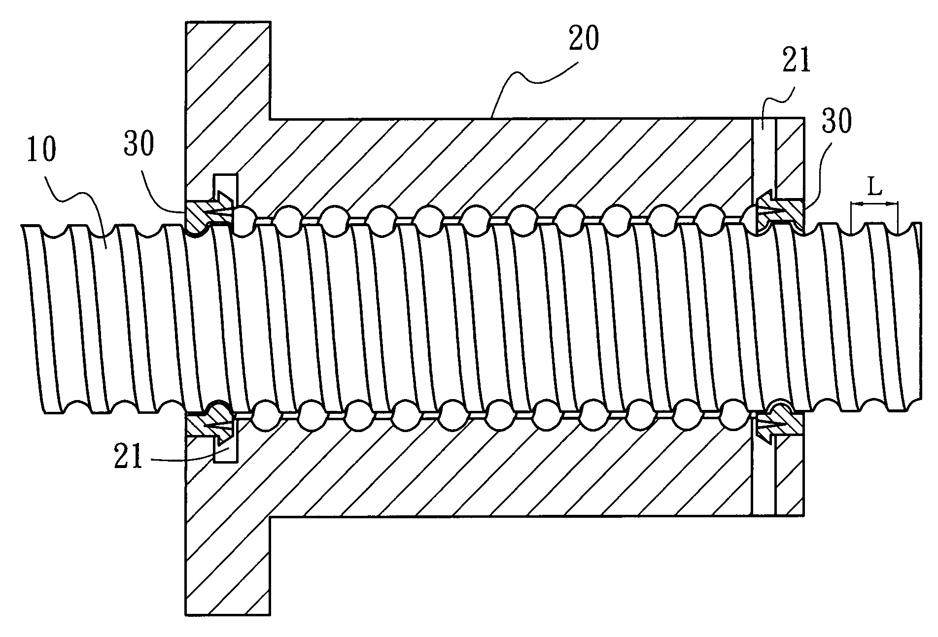
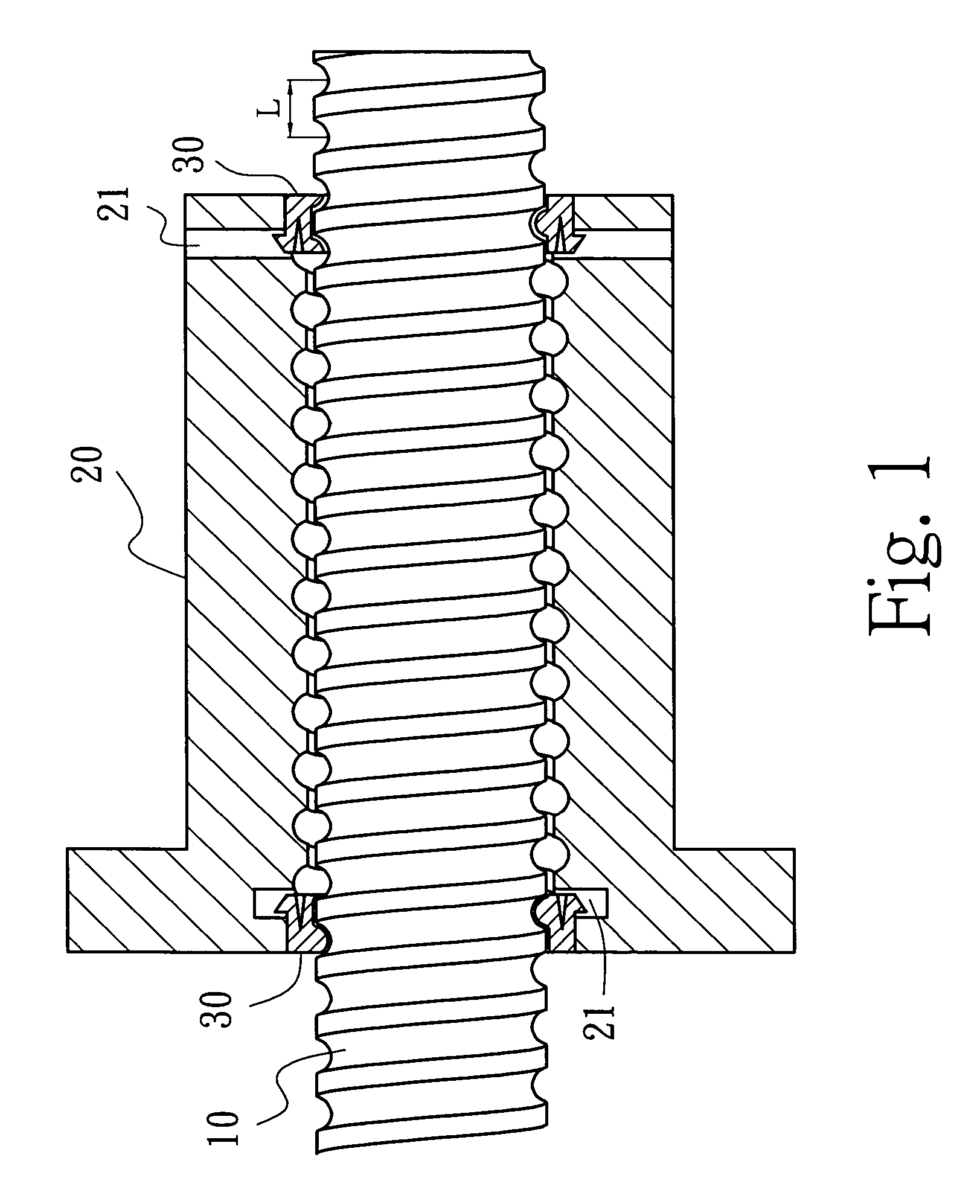
[0009]Accordingly, the present invention is to provide a hooked dust scraper for ball screw unit, which can simplify the fabrication and assembly process so as to curtail the production cost by means of a screwless but just only a hook on structure.
[0010]The hooked dust scraper is the most effective one for removing the foreign materials such as dust, culls and adulterants sticking ahead of the passage of the ball screw unit whose operation relies on the rotation of rolling balls in a spiral groove to push the nut traveling onwards. By attaching the scraper at both incoming and outgoing ends of the ball screw unit to remove the aforesaid foreign materials, the ball screw unit can be operated smoothly and efficiently without the worry of damaging the unit due to excessive abrasion.
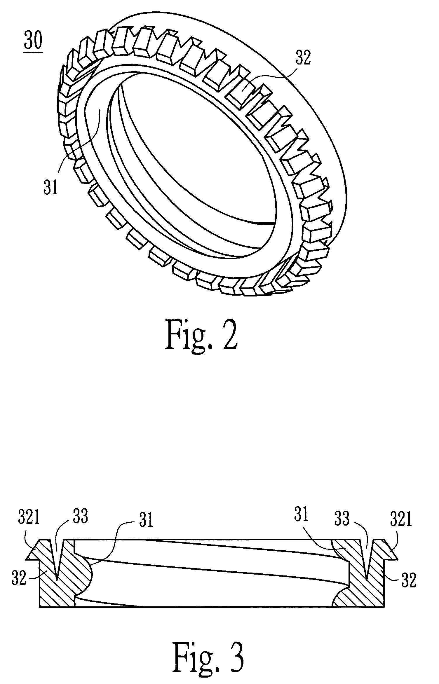
[0011]The main structure of the present invention includes a tooth portion and a hook portion respectively provided at inner and outer sides of the scraper. A plurality of pawls of the hook portion are arrayed along the outer edge of the scraper with a defined pitch such that when the scraper is squeezed beneath the nut of the ball screw unit the pawls may hook on the nut and travel along with the nut without slipping and leave the rest of unhooked pawls maintaining the compressed state thereby enhancing a close attachment of the scraper with screw bolt.
[0012]In the meanwhile, the pitch size of this gear shaped scraper determines the opened angle between two adjacent pawls, hence a proportional relation exists between the rotation angle of the scraper and the longitudinal linear displacement of the scraper along the screw bolt. In view of this, the present invention reserves a clearance between the pawls of the scraper and the adjacent screw bolt thread. The pitch of the screw bolt and the clearance are designed appropriately such that the longitudinal displacement of the scraper per revolution is less than this clearance thereby eliminating mutual interference between the scraper and the screw bolt during operation of the ball screw unit.
[0014]Originally, the present invention provides a scraper only applicable for the ball screw unit with end cut through threaded groove. In order to make the scraper of the present invention applicable for the unit with none end cut through thread groove, an improvement is added to the present invention in which forming a slit on the circumference of the scraper by cutting a small part open thereof. When assembling, pull apart the two sides of the slit a little bit and squeeze the scraper into the spiral groove of the desired ball screw unit. In this manner the pawls are exerted by a small compressive clipping force from the slit which in turn serves to shrink the inner diameter of the scraper and further enhance the close attachment of the scraper to the screw bolt thereby upgrading the applicability and dust prevention effect of the present invention.

Problems solved by technology

However, if the above mentioned foreign materials are stuck on the screw bolt, they might enter the passage of the rolling balls so as to retard the movement of the bolt or even seriously damage the ball screw unit by excessively abrasing the spiral grooves formed between the screw bolt and nut serving as a rolling passage for the balls.
During such tedious machining process, it is probability to happen the defective operations, for example, forgetting to apply one or two screws, piercing accidentally the screw bolt when drilling the screw hole, and unstable installation of the scraper due to its insufficient thickness, etc.
For these defects noticeable on the prior art, an improvement is seriously required.

Method used


Image

  • Hooked dust scraper for ball screw unit
  • Hooked dust scraper for ball screw unit
  • Hooked dust scraper for ball screw unit

Examples


second embodiment

[0029]FIG. 6 shows the present invention. As shown in FIG. 6, tooth portions 41 and hook portions 42 are separately fabricated before assembling to form a unit scraper 40. Each tooth portion 41 has a tooth 411 to mesh the thread of the screw bolt 10 (not shown), and coupling slots 412 at the outer side to be engaged with the corresponding hook portion 42. The hook portion 42 is provided with a plurality of pawls 421 and keys 422 respectively on its outer and inner edges so as to couple with the coupling slots 412. With such a versatile design this two-part separately fabricated scraper is applicable universally for various sized ball screw unit by only selecting a suitable part of tooth portions 41 to meet a ball screw unit having a compatible thread pitch and ball size.

third embodiment

[0030]In the present invention show in FIG. 7, a scraper 50 is also provided with tooth portions 51 and hook portions 52 respectively at its inner and outer sides. A slit 53 is formed at the circumference of the scraper 50 by cutting a small part open thereof. When assembling, the operator may pull apart the two sides of the slit 53 a little bit and squeeze the scraper 50 into the spiral groove of a desired ball screw unit. In this manner the pawls at the outer edge with being about to be squeezed are exerted by a small compressive clipping force of slit 53 which in turn serves to shrink the inner diameter of the scraper 50 and further enhance the close attachment of the scraper 50 to the screw bolt 10 thereby upgrading the applicability and dust preventing effect.

[0031]Various shaped slits provided with the scraper are shown in FIG. 8, and the various shaped pawls provided with the scraper are shown in FIG. 9. As shown in FIG. 8, the slits 53A, B, C are formed between the adjacent ...


PUM


Abstract

A hooked dust scraper for ball screw unit includes a plurality of tooth portions and corresponding number of hook portions. It is characterized that the scraper is hooked on the nut of the ball screw unit without employing screw engagement so that the ball screw unit associated with this scraper is easy to fabricate, assemble, and detach thereby saving the production and assembly cost.

Description

BACKGROUND OF THE INVENTION[0001]1. Field of the Invention[0002]The present invention relates to an improved structure for a scraper to be used with the screw mechanism, in particular, a hooked dust scraper for ball screw unit to effectively prevent possible foreign materials such as dust, culls and adulterates from infringing into the spiral passage of the ball screw unit by removing them in advance ahead of the moving screw nut so as to protect the balls screw unit from excessive abrasion.[0003]2. Description of the Prior Art[0004]A screw mechanism has been applied in the mechanical engineering field for a long time. Basically the rotating motion of a screw bolt is converted to the linear motion of a nut so as to transmit a working piece. Among the existing screw mechanism the ball screw unit is the best efficient one because the traveling of the nut on the screw bolt is carried out by a plurality of balls rolling along the spiral grooves formed therebetween.[0005]However, if the ...

Claims


Application Information

Patent Timeline
Patent Type & Authority Patents(United States)
IPC IPC(8): B65G29/00
CPCF16H25/2418Y10T74/18712F16H25/2204
Inventor YANG, CHUANG-PAOCHEN, YAN-YU
Owner HIWIN TECH
Why Eureka
Try Eureka