Camera module

a technology of camera modules and modules, applied in the field of camera modules, can solve the problems of difficult application of voice coil motor technology, difficult to dispose close proximity, and magnet interference, etc., and achieve the effect of minimizing the gap between the two camera modules, reducing magnetic interference, and minimizing the mutual interference between magnets

Pending Publication Date: 2022-02-03
LG INNOTEK CO LTD
View PDF0 Cites 3 Cited by
  • Summary
  • Abstract
  • Description
  • Claims
  • Application Information

AI Technical Summary

Benefits of technology

[0031]Through the first embodiment, mutual interference between magnets can be minimized in a dual camera module in which CLAF OIS actuators are dually disposed.
[0032]Therefore, it is possible to minimize the gap between the two camera modules.
[0033]The second embodiment can reduce magnetic interference between magnets comprised in two adjacent lens driving apparatuses mounted on a dual camera module, and improve electromagnetic force for performing an AF function, and it is possible to balance the electromagnetic force in the X-axis direction and the electromagnetic force in the Y-axis direction to perform an OIS function.

Problems solved by technology

However, although the need of customers to close the separation distance (gap) of the camera optical axis in the dual camera module is increasing, there is a problem that interference between magnets occurs due to the characteristics of the actuator.
In particular, CLAF OIS is sensitive to magnetic field interference, making it difficult to dispose close proximity.
In addition, since it is difficult to apply the technology of a voice coil motor (VCM) used in a conventional camera module for a camera module for ultra-compact and low power consumption, related studies have been actively conducted.
In the case of a camera module mounted on a small electronic product such as a smartphone, the camera module may be frequently shocked during use, and the camera module may be slightly shaken due to the user's hand shake during photographing.

Method used


Image

  • Camera module
  • Camera module
  • Camera module

Examples


first embodiment

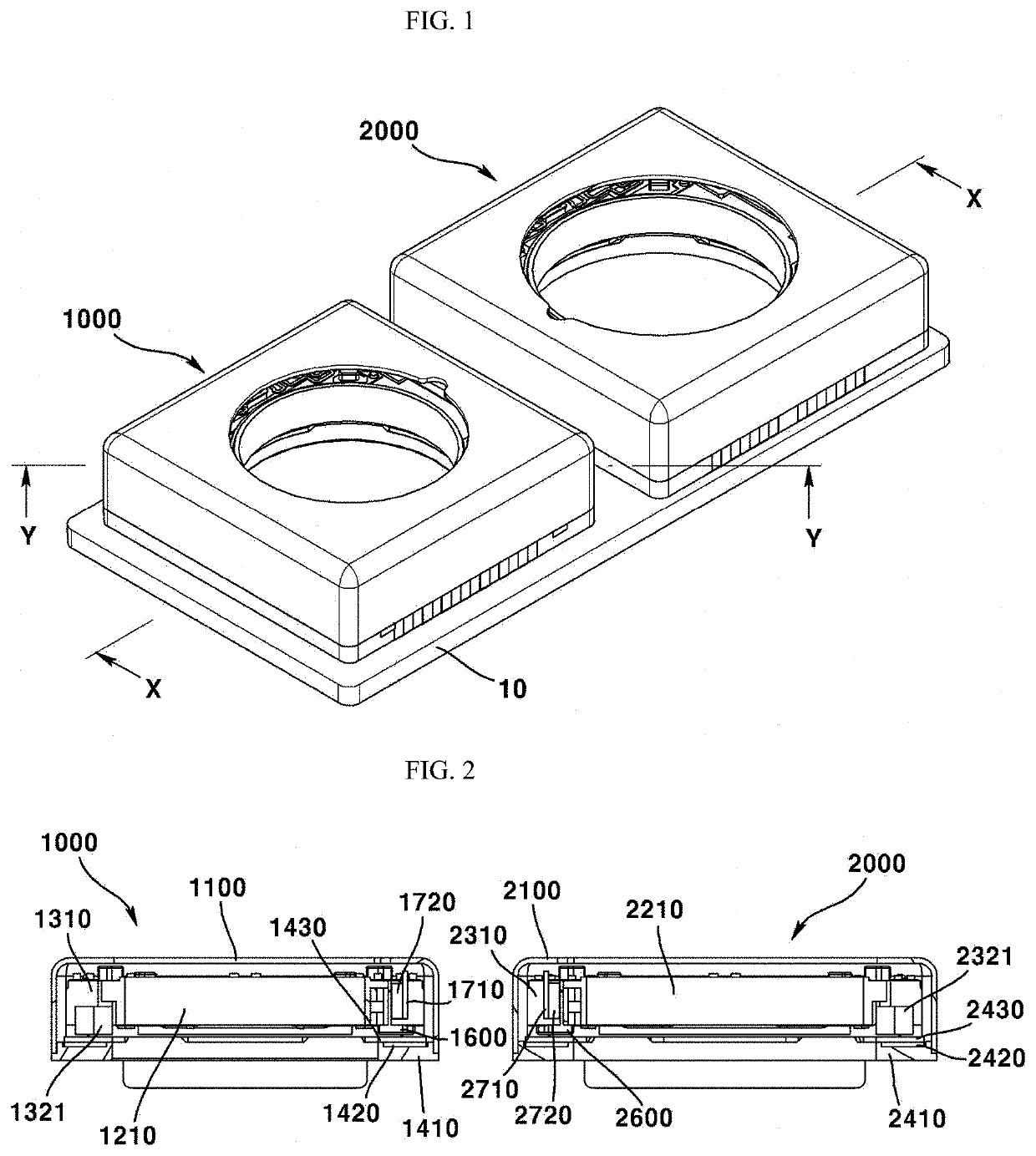
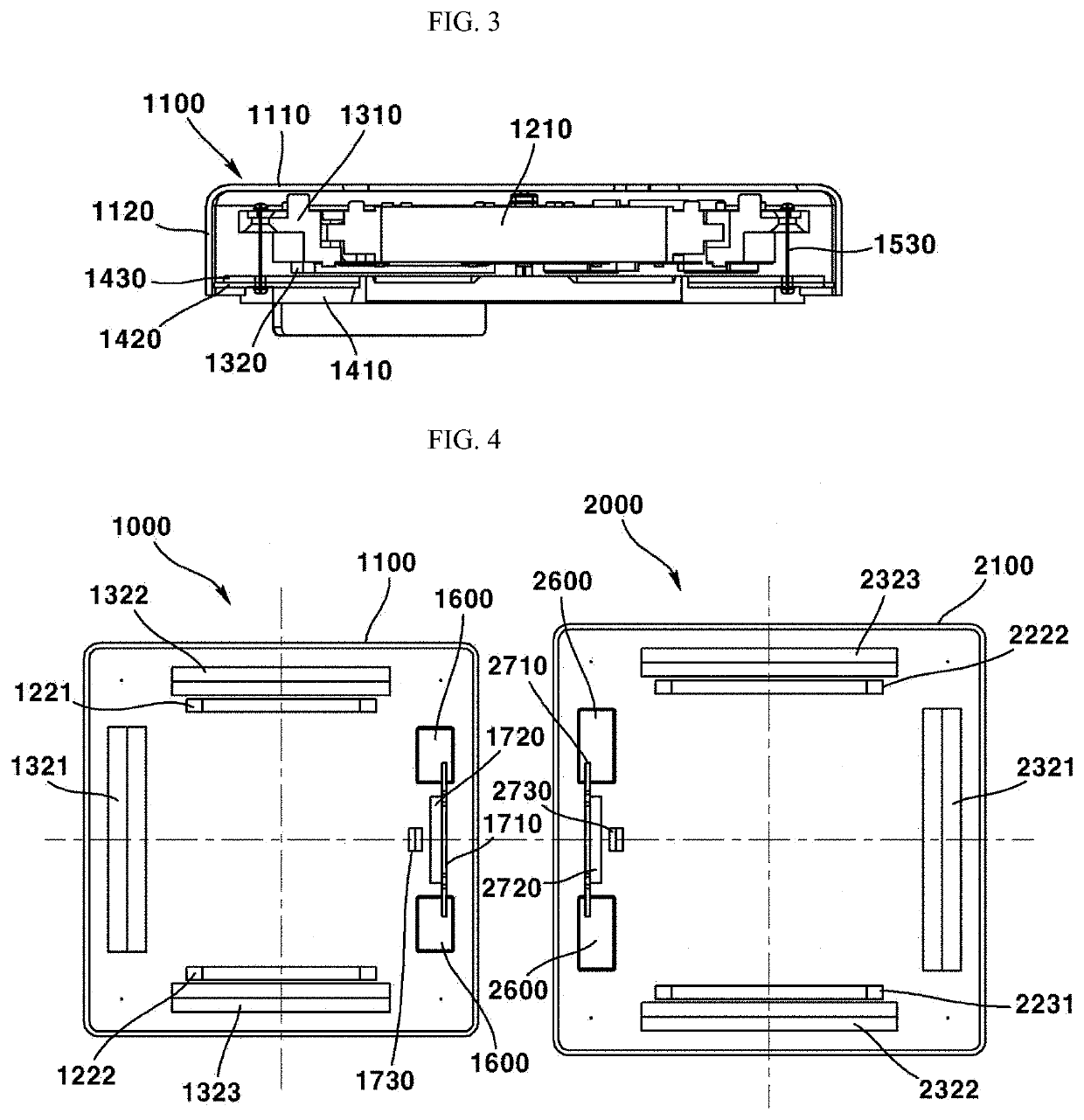
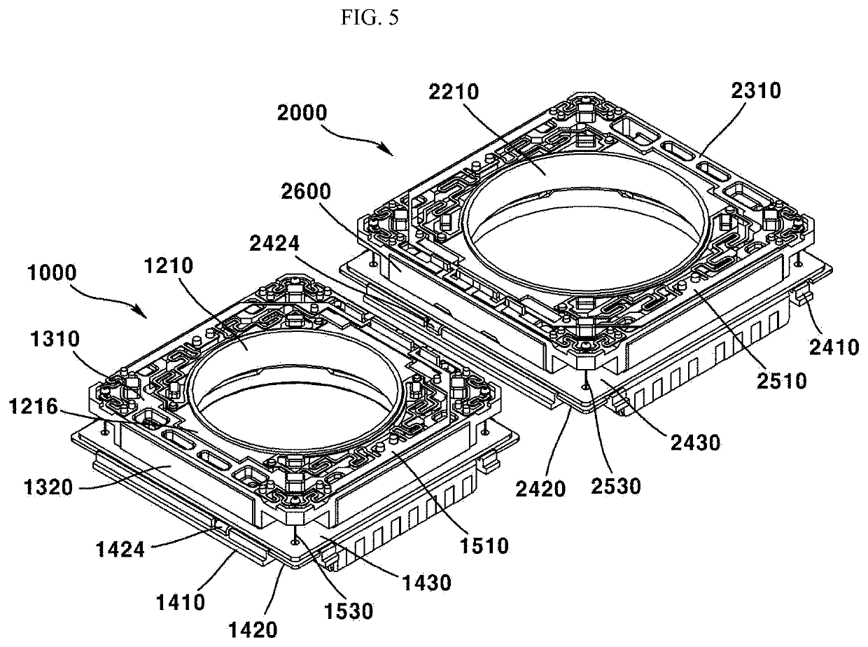
[0008]The first embodiment is to provide a dual camera module capable of minimizing mutual interference between magnets in a structure in which CLAF OIS actuators are disposed in dual.

second embodiment

[0009]The second embodiment is to provide a lens driving apparatus and camera modules and optical devices comprising the same capable of reducing the magnetic field interference between magnets comprised in two adjacent lens driving apparatuses mounted on the dual camera module, improving the electromagnetic force to perform the AF function, and balancing the electromagnetic force in the X-axis direction and the electromagnetic force in the Y-axis direction to perform the OIS function.

Technical Solution

[0010]A camera module according to a first embodiment comprises a first camera module and a second camera module spaced apart from the first camera module, wherein the first camera module comprises: a cover; a housing disposed inside the cover; a bobbin disposed inside the housing; a first coil disposed on the bobbin; a first magnet disposed inside the housing and facing the first coil; a second coil facing the first magnet; a second magnet disposed on the bobbin; and a first sensor d...


PUM


Abstract

A camera module may comprise a first camera module and a second camera module spaced apart from the first camera module, wherein: the first camera module comprises a cover, a housing, a bobbin, a first coil, a first magnet, a second coil, a second magnet, and a first sensor; the first magnet comprises a first-first magnet disposed at a position corresponding to a second lateral plate, a first-second magnet disposed at a position corresponding to a third lateral plate, and a first-third magnet disposed at a position corresponding to a fourth lateral plate; and a first dummy member and the first sensor are disposed at a position corresponding to a first lateral plate of the cover.

Description

CROSS-REFERENCE TO RELATED APPLICATIONS[0001]This application is the U.S. national stage application of International Patent Application No. PCT / KR2019 / 013107, filed Oct. 7, 2019, which claims the benefit under 35 U.S.C. § 119 of Korean Application Nos. 10-2018-0119627, filed Oct. 8, 2018; and 10-2018-0155784, filed Dec. 6, 2018; the disclosures of each of which are incorporated herein by reference in their entirety.TECHNICAL FIELD[0002]This embodiment relates to a camera module.BACKGROUND ART[0003]As various portable terminals are widely spread and commonly used, and the wireless Internet services have been commercialized, the demands of consumer related to portable terminals have been diversified and various kinds of additional devices have been installed in portable terminals.[0004]Among them, there is a camera module for photographing a subject as a photograph or a moving picture. Meanwhile, recently, a dual camera module in which two camera modules are disposed side by side has...

Claims


Application Information

Patent Timeline
Patent Type & Authority Applications(United States)
IPC IPC(8): G02B27/64G03B5/00G02B7/02
CPCG02B27/646G03B2205/0007G02B7/02G03B5/00G02B7/08G02B13/001G03B30/00G03B19/22G03B2205/0069G03B3/10H04N23/54H04N23/45H04N23/57H04N23/55
Inventor MIN, SANG JUNPARK, SANG OK
Owner LG INNOTEK CO LTD
Why Eureka
Try Eureka