Optical inspection apparatus and method

a technology of optical inspection and scanning equipment, applied in the direction of measurement devices, instruments, television systems, etc., can solve the problems of increasing the overall dimensions of the inspection system, mutual scanning interference between the profile sensors, etc., to prevent mutual scanning interference, and prevent mutual scanning interference

Active Publication Date: 2014-05-13
CENT DE RES & DEV IND DU QUEBEC
View PDF27 Cites 4 Cited by
  • Summary
  • Abstract
  • Description
  • Claims
  • Application Information

AI Technical Summary

Benefits of technology

[0003]There is a main object of the present invention to provide apparatus and methods for simultaneously scanning the profile of at least two adjacent surfaces of an article moving along a travel path axis passing through an inspection area, which prevent mutual scanning interference between the profile sensors used while providing a compact arrangement thereof.
[0004]According to the above-mentioned main object, from a broad aspect of the present invention, there is provided an optical inspection apparatus for simultaneously scanning the profile of at least two adjacent surfaces of an article moving along a travel path axis passing through an inspection area located at a central plane transverse to the travel path axis. The apparatus comprises a first profile sensor unit having a first optical sensing field directed toward the travel path axis and defining a first scanning zone associated with a first one of the adjacent surfaces as intersected by the first sensing field, and a first laser source directing at angle with the first sensing field a first fan-shaped laser beam toward the first scanning zone to define an associated first scanning plane transverse to the travel path axis, to generate first sensor output data related to the profile of the first article surface. The apparatus further comprises a second profile sensor unit having a second optical sensing field directed toward the travel path axis and defining a second scanning zone associated with a second one of the adjacent surfaces as intersected by the second sensing field, and a second laser source directing at angle with the second sensing field a second fan-shaped laser beam toward the second scanning zone to define an associated second scanning plane transverse to the travel path axis, to generate second sensor output data related to the profile of the second article surface. In the apparatus, the first and second profile sensor units are disposed one with respect to another so that their respective first and second scanning zones are sufficiently spaced one with another along the travel path axis to substantially prevent mutual scanning interference between the first and second profile sensor units, and one of the first sensing field and the first laser beam is crossing the central plane toward the other one of the first sensing field and the first laser beam, one of the second sensing field and the second laser beam is crossing the central plane toward the other one of the second sensing field and the second laser beam, to provide a compact arrangement of the first and second profile sensor units.
[0005]According to the same main object, from another broad aspect, there is provided an optical method for simultaneously scanning the profile of at least two adjacent surfaces of an article moving along a travel path axis passing through an inspection area located at a central plane transverse to the travel path axis. The method comprises the steps of: directing a first optical sensing field of a first profile sensor toward the travel path axis, the first sensing field defining a first scanning zone associated with a first one of the adjacent surfaces as intersected by the first sensing field; directing at angle with the first sensing field a first fan-shaped laser beam toward the first scanning zone to define an associated first scanning plane transverse to the travel path axis, causing the first profile sensor to generate first sensing output data related the profile of the first article surface; directing a second optical sensing field of a second sensor toward the travel path axis, the second sensing filed defining a second scanning zone associated with a second one of the adjacent surfaces as intersected by the second sensing field; directing at angle with the second sensing field a second fan-shaped laser beam toward the second scanning zone to define an associated second scanning plane transverse to the travel path axis, causing the second profile sensor to generate second sensor output data related the profile of the second article surface; wherein the first and second scanning zones are sufficiently spaced one with another along the travel path axis to substantially prevent mutual scanning interference between the first and second profile sensors; and one of the first sensing field and the first laser beam is crossing the central plane toward the other one of the first sensing field and the first laser beam, one of the second sensing field and the second laser beam is crossing the central plane toward the other one of the second sensing field and the second laser beam, to provide a compact arrangement of the first and second profile sensors.

Problems solved by technology

A problem with the known systems is that mutual scanning interference between the profile sensors may occur, due to the relative proximity of the laser beams generated by the profile sensors.
However, such basic approach for the design of the profile sensor arrangement tends to increase the overall dimensions of the inspection system.

Method used


Image

  • Optical inspection apparatus and method
  • Optical inspection apparatus and method
  • Optical inspection apparatus and method

Examples


Embodiment Construction

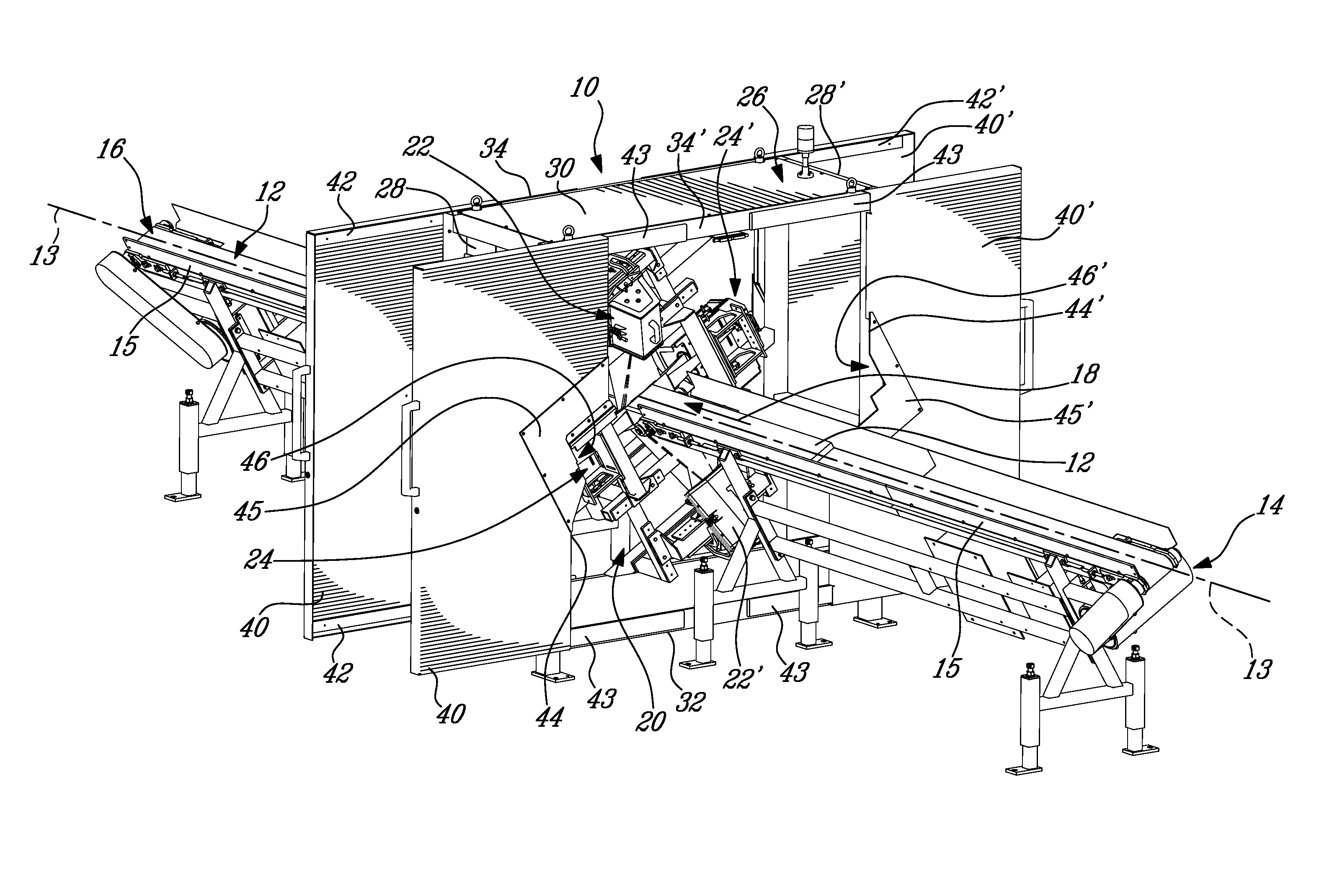
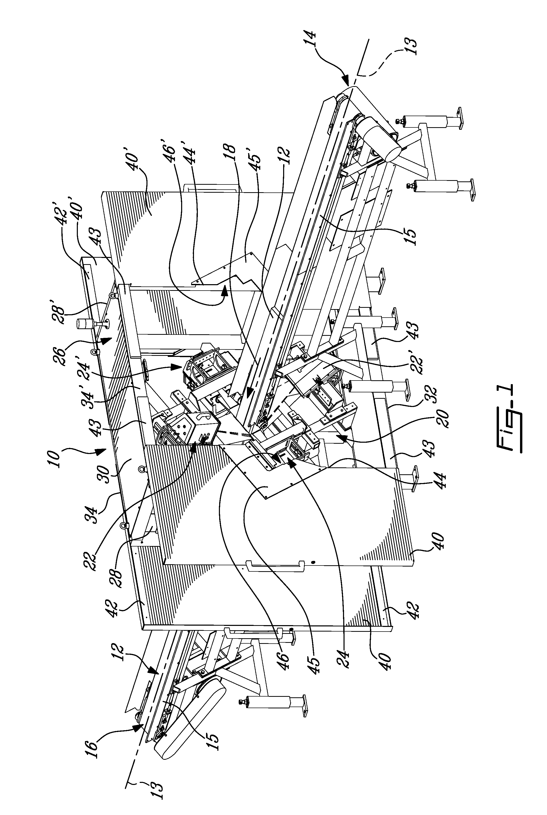
[0019]Referring now to FIG. 1, there is shown an example of inspection apparatus as generally designated at 10, which is designed for simultaneously scanning the profile of four adjacent surfaces of an article 12, which is a wooden board to be inspected in the present example. It is to be understood that the optical inspection apparatus and method as described below may be used to inspect articles of any nature, material or shape. The profile data can be used to detect profile-related board characteristics including geometrical and surface defects such as wane, holes, knots, cracks etc., using known detection techniques such as disclosed in prior U.S. published Patent application no. 2010 / 0188500 and U.S. Pat. No. 6,122,065 naming the same assignee as of the present invention. The detected characteristics are typically fed to a cut optimizer software providing a cutting solution into subdivided products from each board, producing an optimum yield in term of either economic value or ...


PUM


Abstract

An optical apparatus and method for simultaneously scanning the profile of at least two adjacent surfaces of an article such as a wooden board moving along a travel path axis passing through an inspection area located at a central plane transverse to the travel path axis, involve first and second scanning zones sufficiently spaced one with another along the travel path axis to substantially prevent mutual scanning interference between the profile sensors used, while providing a compact arrangement of profile sensors. For so doing, one the first sensing field and the first laser beam of the first profile sensor is crossing the central plane toward the other one of the first sensing field and the first laser beam, and one the second sensing field and the second laser beam of the second profile sensor is crossing the central plane toward the other one of the second sensing field and the second laser beam.

Description

FIELD OF THE INVENTION[0001]The present invention relates to the field of optical inspection technologies, and more particularly to optical inspection apparatus and method for scanning articles using laser profile sensors.BACKGROUND OF THE INVENTION[0002]During the past years, systems for scanning the surface of moving articles have been developed and applied for grading or quality control purposes in many high volume manufacturing applications such as found in the automotive, consumer electronics, agricultural, food or lumber processing industries. Such scanning systems typically use profile sensors based on laser triangulation to measure geometrical and other 3D surface characteristics of the inspected articles. Examples of such known scanning systems are disclosed in U.S. published patent applications no. 2007 / 0263918 A1 and no. 2004 / 0246473 A1. In some applications, there is a need for simultaneously scanning the profile of two adjacent surfaces provided on articles moving along...

Claims


Application Information

Patent Timeline
Patent Type & Authority Patents(United States)
IPC IPC(8): G01B11/245
CPCG01B11/245
Inventor LESSARD, DENIS
Owner CENT DE RES & DEV IND DU QUEBEC
Why Eureka
Try Eureka