

Touch controller for touch-sensing display apparatus and driving method thereof
a touch controller and display device technology, applied in the direction of instruments, computing, electric digital data processing, etc., can solve the problems of serious and achieve the effect of avoiding interference between the touch panel and the display panel
- Summary
- Abstract
- Description
- Claims
- Application Information
AI Technical Summary
Benefits of technology
Problems solved by technology
Method used
Image

Examples
first embodiment
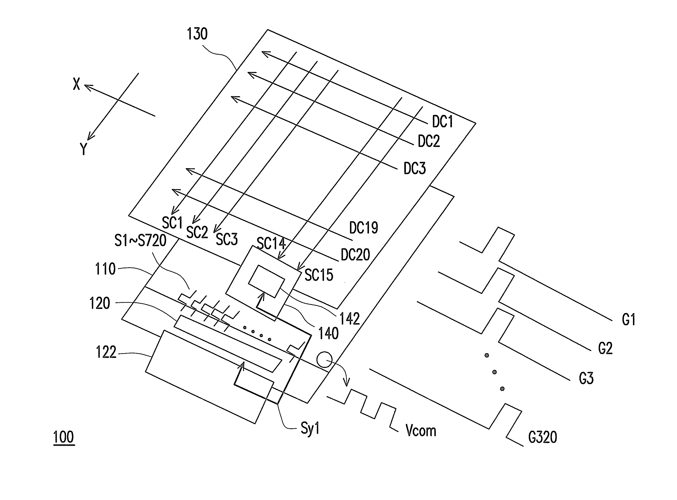
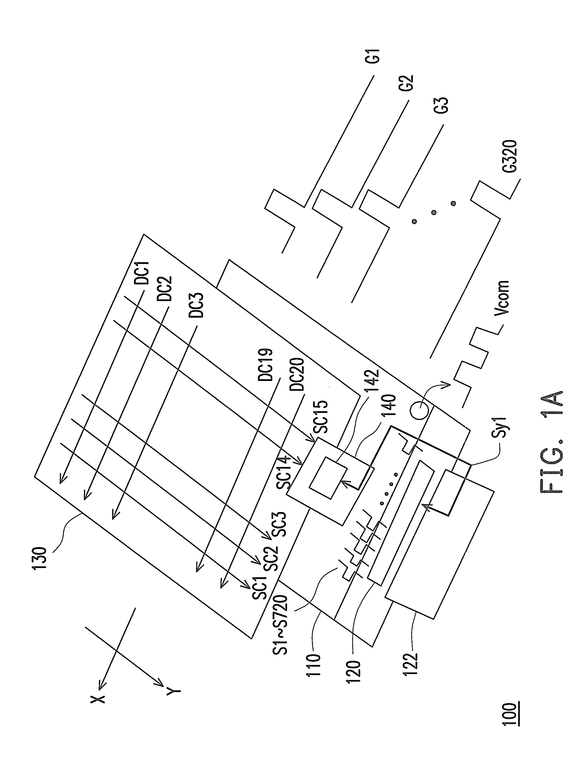
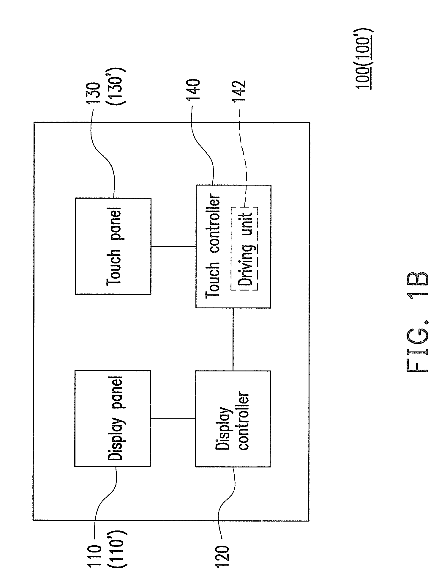
[0033]FIG. 1A is a schematic diagram of a touch display apparatus according to the first embodiment of the invention. FIG. 1B is a block schematic diagram of the touch display apparatus according to the first embodiment of the invention.
[0034]Referring to FIG. 1A and FIG. 1B, in the present embodiment, the touch display apparatus 100 includes a display panel 110, a display controller 120, a touch panel 130 and a touch controller 140. The touch panel 130 is integrated with the display panel 110 in the same touch display apparatus, and is disposed on the display panel 110, as that shown in FIG. 1A. Moreover, in the present embodiment, the touch controller 140 includes a driving unit 142, which is coupled to the display panel 110 and the touch panel 130 for driving the touch panel 130 to perform touch sensing, as that shown in FIG. 1B.
[0035]The display panel 110 includes a plurality of display scan lines and a plurality of data lines. When the display panel 110 is driven, the display s...
second embodiment
[0047]FIG. 3 is a schematic diagram of a touch display apparatus according to the second embodiment of the invention. Referring to FIG. 1A, FIG. 1B and FIG. 3, the touch display apparatus 100′ of the present embodiment is similar to the touch display apparatus 100 of the first embodiment, and a main difference there between lies in arranging methods of display scan lines of a display panel 110′ and touch scan lines of a touch panel 130′ and a driving method of the touch display apparatus 100′. Moreover, the block schematic diagram of the touch display apparatus 100′ is as that shown in FIG. 1B.
[0048]In detail, the display panel 110′ includes a plurality of display scan lines and a plurality of data lines. When the display panel 110′ is driven, the display scan lines sequentially receive corresponding scan signals G1-G640 for driving pixel units connected to the data lines to sequentially receive data signals S1-S1440. It should be noticed that for simplicity's sake, the display scan...
third embodiment
[0060]FIG. 5 is a flowchart illustrating a driving method of a touch display apparatus according to the third embodiment of the invention. Referring to FIG. 5, the driving method includes following steps.
[0061]In step S500, I scan signals are sequentially sent to drive the display panel to receive a plurality of data signals. In step S502, M driving signals are sequentially sent to drive the touch panel to generate a plurality of sensing signals during a sensing period. In step S504, an mth driving signal is synchronized with an ith scan signal, where 1≦i≦I and 1≦m≦M. In step S506, the touch panel is delayed by a predetermined time period within each pulse width of the M driving signals for generating the sensing signals.
[0062]Moreover, since those skilled in the art can learn enough instructions and recommendations of the driving method of the invention from the descriptions of the first embodiment and the second embodiment, detailed description thereof is not repeated.
[0063]In sum...
PUM
 Abstract
Description
Claims
Application Information