Inductive charging system for electric vehicle

a charging system and electric vehicle technology, applied in the field of electric vehicle charging systems, can solve the problems of insufficient charging, insufficient charging, and insufficient charging, and achieve the effect of safe, simple and efficient charging

Active Publication Date: 2015-01-20
PHILIPS IP VENTURES BV
View PDF83 Cites 49 Cited by
  • Summary
  • Abstract
  • Description
  • Claims
  • Application Information

AI Technical Summary

Benefits of technology

[0005]In a third aspect of the invention, the primary charging coil is in fixed longitudinal registration with the wheel chock. The primary coil is located such that, when the wheels of the vehicle contact the wheel chock, the primary coil is aligned with the secondary coil in the vehicle. Additionally, the primary and secondary coils are generally horizontal or angled from horizontal to facilitate damage-free coupling and decoupling of the coils during movement of the vehicle into and out of the charging system.

Problems solved by technology

Inductive charging systems can experience efficiency issues if 1) the primary coil and secondary coil are not adequately aligned with one another and / or 2) the coils are not sufficiently proximate one another.
Unfortunately, those designs are relatively complex and often include relatively delicate sensing and movement systems, which may require calibration and maintenance over time.
Further, an animal or other moving object may wander between the primary and secondary coils, which may interfere with the efficiency of the coupling between the primary and secondary coil.

Method used


Image

  • Inductive charging system for electric vehicle
  • Inductive charging system for electric vehicle
  • Inductive charging system for electric vehicle

Examples


first embodiment

I. First Embodiment

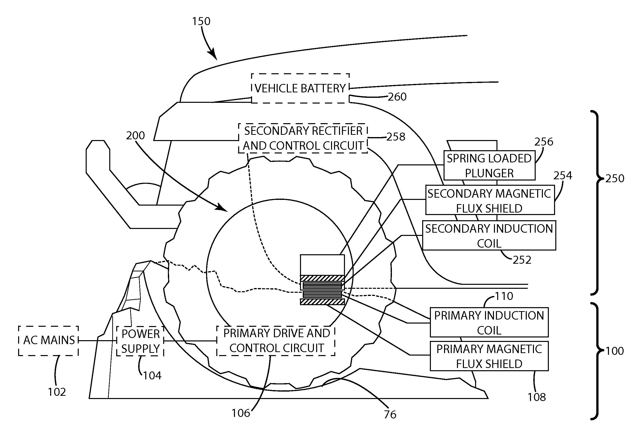
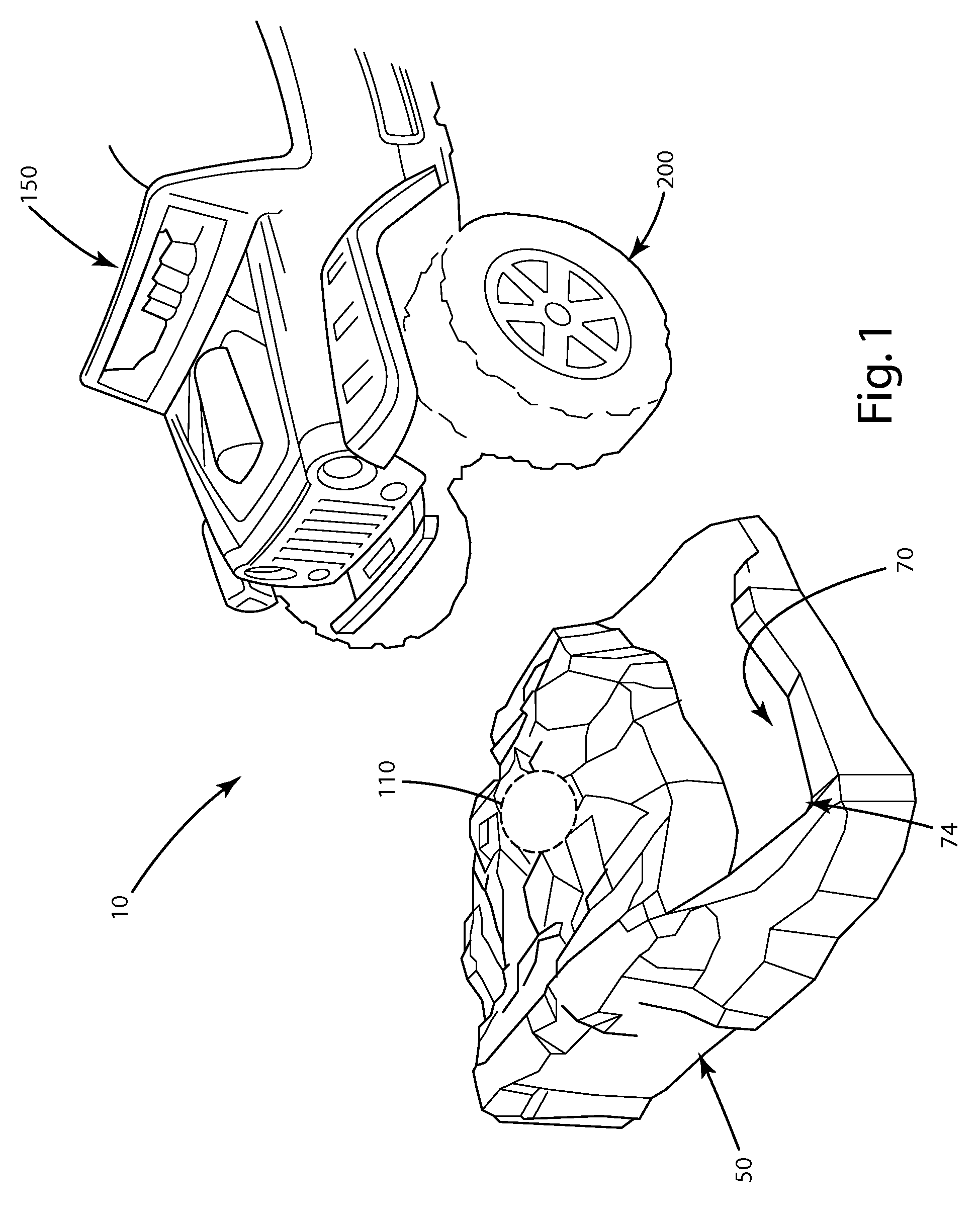
[0081]A first embodiment of the inductive vehicle charging system of the present invention is illustrated in the drawings and generally designated 10. The charging system 10 includes wheel chocks 50 and a vehicle 150. The wheel chocks 50 include alignment tracks 70 and a charging circuit 100. The vehicle 150 includes wheels 200 that align with the alignment tracks 70. The vehicle 150 includes a battery circuit 250.

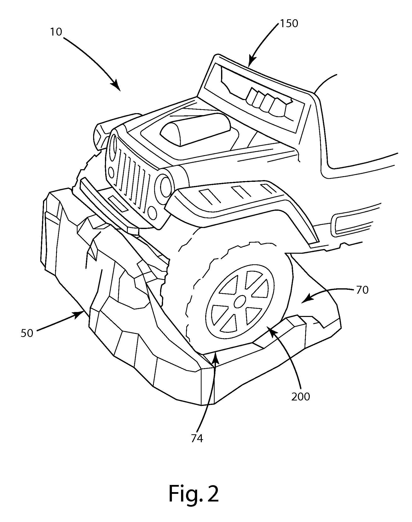
[0082]As shown in FIGS. 1-3, the charging system 10 includes wheel chocks 50, alignment tracks 70, a primary charging coil 110, and a secondary coil 252. In FIG. 1, a toy vehicle 150 is shown with the wheels 200 aligned with the alignment tracks 70 as the toy vehicle 150 approaches the wheel chocks 50. The wheels 200 of the toy vehicle 150 enter the alignment tracks 70 and the toy vehicle 150 proceeds forward. The alignment tracks 70 terminate at front walls 74. After the wheels 200 contact the front walls 74 of the alignment tracks 70, the forward movem...

second embodiment

II. Second Embodiment

[0087]A second embodiment of the present invention is shown in FIG. 5. In this embodiment, the primary charging coil 110 is separated from the wheel chocks 50′ and mounted on a charging block 210. The vehicle 150″ moves forward until the wheels 200 contact the wheel chocks 50′ and the forward movement of the vehicle 150″ is impeded. This embodiment is designed such that, when the wheels 200 contact the wheel chocks 50′, the primary charging coil 110 and secondary coil 252 are in proper inductive charging alignment relative to one another. As shown in FIG. 5, the primary charging coil 110 and secondary coil 252 are generally horizontal, but at a slight angle relative to the road surface 300. This allows the secondary coil 252 to couple with and uncouple from the primary charging coil 110 during relative longitudinal movement of the vehicle and the charger. This arrangement also prevents damage to the coils 110, 252 if the vehicle 150″ unexpectedly moves rearward ...

third embodiment

III. Third Embodiment

[0088]A third embodiment of the invention is shown in FIGS. 6a and 6b. In this embodiment, the wheel chock 50″ includes a well 76′ and a hinge pin 92. A charging pedal 80 is hingedly connected to wheel chock 50″ at hinge pin 92. The charging pedal 80 includes a curved, rigid lever 82 with a forward portion 84 and a rearward portion 86. A primary coil platform 88 is hingedly connected to the lever 82 with hinge 90. Within hinge 90 is a hinge stop that prohibits the primary coil platform 88 from pivoting about hinge 90 past a predetermined platform angle θ relative to the rearward portion 86 of lever 82. Optionally, any other suitable device to prohibit platform 88 from pivoting about hinge 90 past platform angle θ may be used. Platform angle θ will be further described below. The primary charging coil 110 is positioned on the top surface of primary coil platform 88.

[0089]If a vehicle 150″ is not present, the wheel chock 50″ will have the orientation shown in FIG....


PUM

PropertyMeasurementUnit
frequencyaaaaaaaaaa
frequencyaaaaaaaaaa
frequencyaaaaaaaaaa

Abstract

A charging system for an electric vehicle that assists in aligning a primary charging coil and a secondary coil. The system may include a wheel chock that raises the primary coil into alignment with the secondary coil when a tire enters the wheel chock. The system may include a primary that is recessed below the surface supporting the vehicle and is protected by a cover. The secondary coil may be protected and supported by a skid plate mounted to the vehicle. The system may include a charging circuit that is controlled by signals transmitted by a garage door opener transmitter or a garage door opener. The system may include sensors that detect the presence of an animal or object in the space between the primary coil and the secondary coil.

Description

BACKGROUND OF THE INVENTION[0001]The present invention relates to charging systems for electric vehicles and more particularly to charging system that provide improved alignment between the primary coil and the secondary coil.[0002]Inductive power is used in a variety of vehicle charging applications. These systems include a primary charging coil connected to a power source and a secondary coil within the vehicle connected to a battery. Power is applied to the primary charging coil, which induces a current in the secondary coil to charge the battery. Inductive charging systems can experience efficiency issues if 1) the primary coil and secondary coil are not adequately aligned with one another and / or 2) the coils are not sufficiently proximate one another. Prior art designs include a variety of techniques for aligning the coils and / or moving the coils into physical proximity. Unfortunately, those designs are relatively complex and often include relatively delicate sensing and moveme...

Claims


Application Information

Patent Timeline
Patent Type & Authority Patents(United States)
IPC IPC(8): B60L11/18H02J7/02H01F38/14H02J7/00H04B5/00
CPCB60L11/1846H02J7/0042B60L11/1829Y04S30/14Y02T90/14B60L11/1833H01F38/14Y02T90/128B60L11/182H04B5/0037B60L2270/36Y02T10/7005Y02T90/121Y02T90/122H02J7/025Y02T90/125H04B5/0075Y02T90/169B60L2200/26B60L2230/16Y02T10/7088Y02T90/163G01R29/0814H02J7/0052H02J5/005B60L53/38B60L53/36B60L53/65B60L53/305B60L53/124B60L53/126B60L53/122H02J2310/48H02J50/10H02J50/90Y02T10/7072Y02T90/12Y02T90/167Y02T90/16Y02T10/70H02J7/0027B60L53/12B60L53/35H02J50/60H02J50/12B60Y2200/91B60Y2400/30H02J7/00
Inventor BAARMAN, DAVID W.EURICH, SEAN T.STONER, JR., WILLIAM T.TAYLOR, JOSHUA B.WEBER, RICHARD J.LORD, JOHN J.BACHMAN, WESLEY J.ZELLERS, KRISTEN J.LORD, SHAWN C.
Owner PHILIPS IP VENTURES BV
Why Eureka
Try Eureka