Pixel structure of electroluminescent display panel

a technology pixel structure, which is applied in the direction of thermoelectric device junction materials, electrical equipment, and semiconductor devices, etc., can solve the problems of large power consumption of electroluminescent display panel, about 50% of light loss, and poor color gamut, and achieve low power consumption and good color saturation

Active Publication Date: 2015-02-03
AU OPTRONICS CORP
View PDF8 Cites 10 Cited by
  • Summary
  • Abstract
  • Description
  • Claims
  • Application Information

AI Technical Summary

Benefits of technology

[0005]It is therefore one of the objective of the present invention to provide a pixel structure of an electroluminescent display panel having good color saturation and with low power consumption.

Problems solved by technology

However, since the white light has a wide spectrum, the filtered red light, green light and blue light from the color filters are not saturated enough, such that the color gamut is not good enough.
Besides, the color filters cause about 50% of light loss, thus the power consumption of the electroluminescent display panel is greatly raised.

Method used


Image

  • Pixel structure of electroluminescent display panel
  • Pixel structure of electroluminescent display panel
  • Pixel structure of electroluminescent display panel

Examples


Embodiment Construction

[0019]To provide a better understanding of the present invention to the skilled users in the technology of the present invention, preferred embodiments will be detailed as follows. The preferred embodiments of the present invention are illustrated in the accompanying drawings with numbered elements to elaborate on the contents and effects to be achieved.

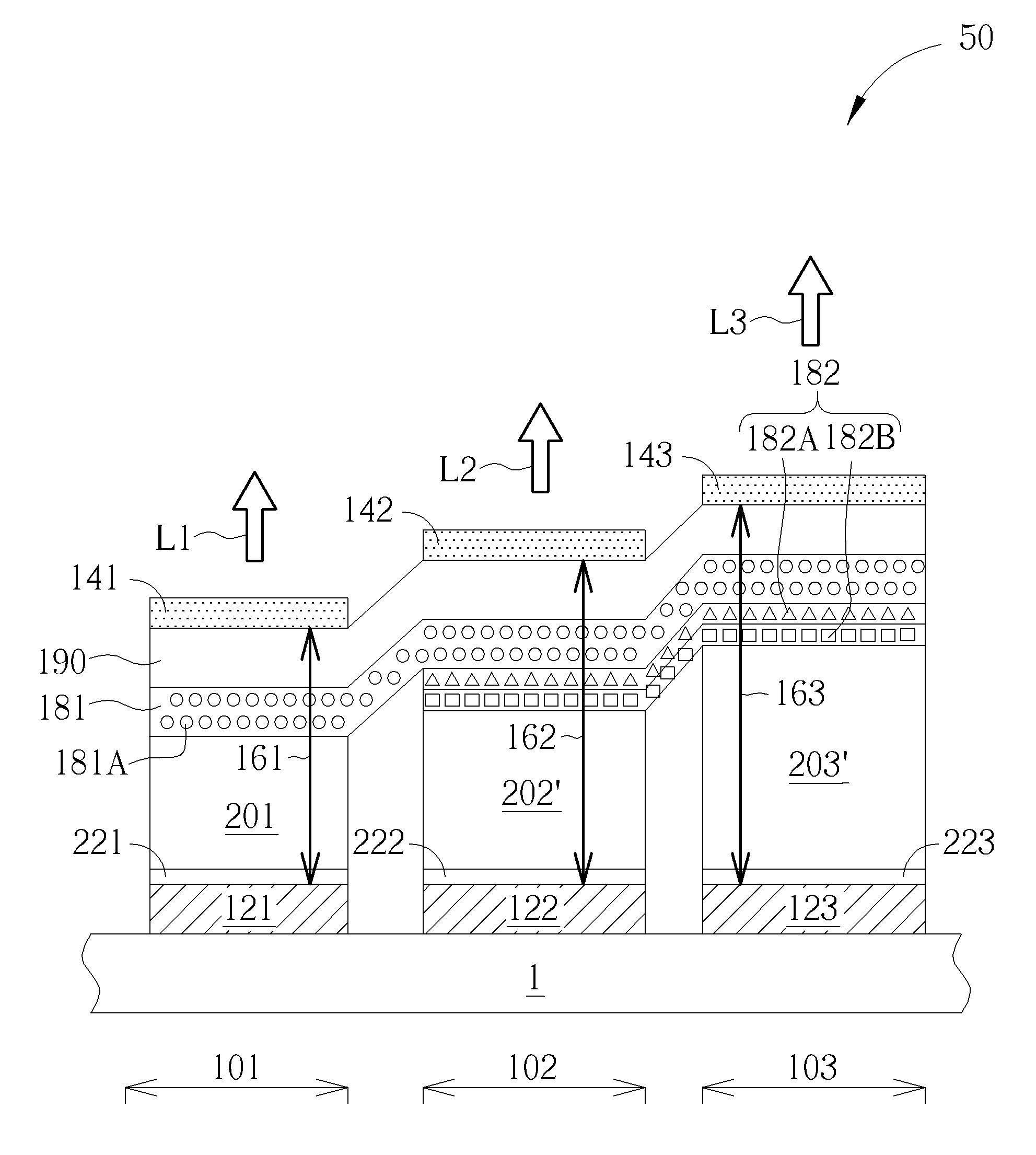
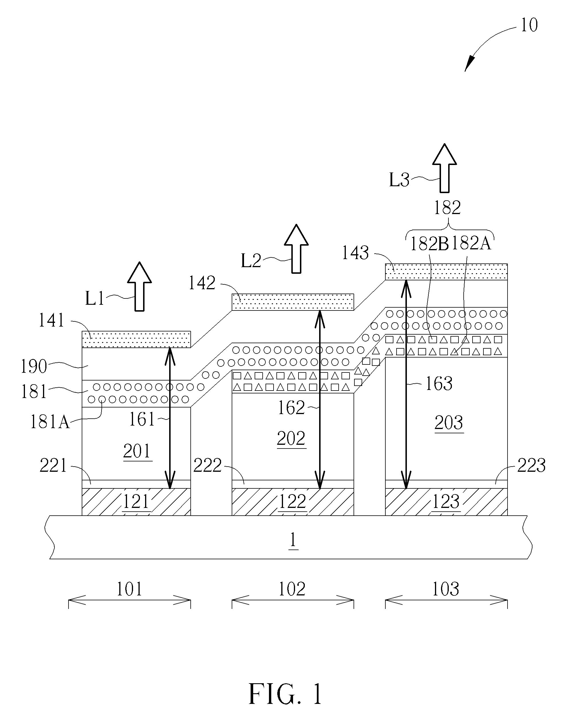
[0020]Please refer to FIG. 1. FIG. 1 is a schematic diagram of a pixel structure of an electroluminescent display panel according to a first preferable embodiment of the present invention. As shown in FIG. 1, the pixel structure 10 of the electroluminescent display panel of this embodiment has a first sub-pixel region 101, a second sub-pixel region 102 and a third sub-pixel region 103, or the pixel structure 10 of the electroluminescent display panel of this embodiment is composed of the first sub-pixel region 101, the second sub-pixel region 102 and the third sub-pixel region 103, for displaying different color lights respectively. ...


PUM


Abstract

A pixel structure of electroluminescent display panel has a first sub-pixel region, a second sub-pixel region and a third sub-pixel region. The pixel structure of electroluminescent display panel includes a first organic light-emitting layer and a second organic light-emitting layer. The first organic light-emitting layer, which includes a first organic light-emitting material, is disposed at least in the first sub-pixel region and the second sub-pixel region. The second organic light-emitting layer, which includes a second organic light-emitting material and a third organic light-emitting material, is disposed at least in the second sub-pixel region and the third sub-pixel region. The first organic light-emitting layer and the second organic light-emitting layer overlap in the second sub-pixel region. The first sub-pixel region and the third sub-pixel region have different cavity lengths.

Description

BACKGROUND OF THE INVENTION[0001]1. Field of the Invention[0002]The present invention is related to a pixel structure of an electroluminescent display panel, and more particularly, related to a pixel structure of an electroluminescent display panel that is no need of color filter for displaying image.[0003]2. Description of the Prior Art[0004]Due to its self-luminous, high contrast ratio, compact size, and wide viewing angle properties, electroluminescent display panel e.g. organic light-emitting diode (OLED) display panel has been expected to prevail in the display market of next generation. In conventional full-color electroluminescent display panel, white light organic light-emitting layer is mainly used for generating white light and then color filters are used for filtering the white light to form three different primary color lights, such as red light, green light and blue light, so as to display full-color display image. However, since the white light has a wide spectrum, the...

Claims


Application Information

Patent Timeline
Patent Type & Authority Patents(United States)
IPC IPC(8): H01L27/32
CPCH01L27/3211H01L27/3213H01L27/3218H10K59/351H10K50/13H10K50/852H10K59/35H10K59/353
Inventor LEE, MENG-TINGCHU, MIAO-TSAI
Owner AU OPTRONICS CORP
Why Eureka
Try Eureka