Liquid crystal display

Active Publication Date: 2009-05-28
AU OPTRONICS CORP
View PDF6 Cites 10 Cited by
  • Summary
  • Abstract
  • Description
  • Claims
  • Application Information

AI Technical Summary

Benefits of technology

[0022]In summary, the present invention multiplies the optical spectrum of a filter layer by the transmission spectrum of the backlight module, then multiplies the product by a color matching function and th

Problems solved by technology

However, a common white LED is usually implemented by using a blue LED chip in association with an YAG (yttrium aluminum garnet) phosphor because the white LED including the blue LED chip and YAG phosphor has the advantages of packaging convenience and small size, but the color saturation of the white LED is still not good enough.
In particular, in contrast with a CCFL backl

Method used


Image

  • Liquid crystal display
  • Liquid crystal display
  • Liquid crystal display

Examples


Example

The First Embodiment

[0037]FIG. 2A is a locally-large cross-section diagram of an LCD according to the present invention. Referring to FIG. 2A, an LCD 100 of the embodiment includes a backlight module 110 and an LCD panel 120, wherein the backlight module 110 has at least a white light source 112, and the normalized optical spectrum of the backlight module 110 is BL(λ). The LCD panel 120 is disposed over the backlight module 110. The LCD panel 120 includes two substrates and a liquid crystal layer 130 located between the two substrates, wherein one of the two substrates has a red color filter layer 122, a green color filter layer 124 and a blue color filter layer 126. The present invention does not limit the type of the white LED. In fact, the white LED can be a white LED composed of a blue LED and YAG, a white LED composed of a plurality of LEDs able to emit different color light or a white LED of other types.

[0038]In the embodiment, the normalized optical spectrum of the backlight ...

Example

The Second Embodiment

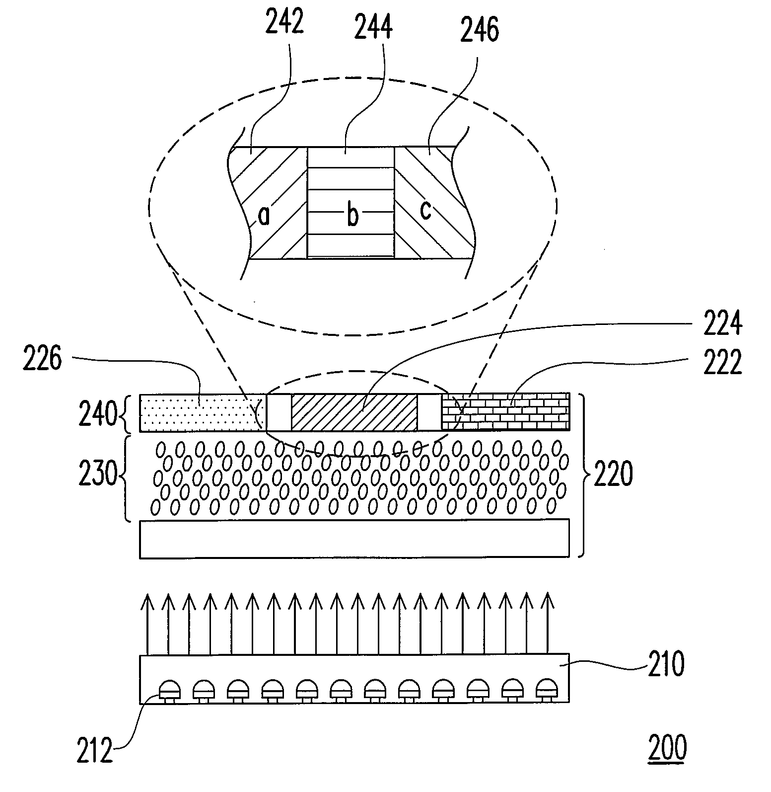
[0042]FIG. 3A is a locally-large cross-section diagram of an LCD according to the present invention. The LCD 200 of the embodiment is similar to the LCD 100, except that the middle color filter layer of the LCD 200 includes at least one of a green color filter layer 242, a cyan color filter layer 244 and a yellow color filter layer 246, while other two color filter layers 222 and 226 are the same as 122 and 126 in FIG. 2A.

[0043]FIG. 3B is a locally top view of the color filter layer 224 of FIG. 3A. Referring to FIG. 3B, the areas proportion of the green color filter layer 242, the cyan color filter layer 244 and the yellow color filter layer 246 is a:b:c. Since the color filter layer 224 includes three color filter layers with different colors and different transmittance, thus the effective transmission spectrum of the color filter layer 224 is defined by CFx(λ), wherein the effective transmission spectrum of the green color filter layer 242 is defined by CFGree...

Example

The Third Embodiment

[0047]FIG. 4 is a locally-large cross-section diagram of an LCD according to the present invention. Referring to FIG. 4, an LCD 300 of the embodiment includes a backlight module 310 and an LCD panel 320, wherein the backlight module 310 has at least a white light source 112 disposed thereon, the white light source 312 is, for example, a white LED or a white organic LED and the normalized optical spectrum of the backlight module 310 is BL(λ). The LCD panel 320 is disposed over the backlight module 310. The LCD panel 320 includes two substrates and a liquid crystal layer 330 located between the two substrates, wherein one of the two substrates has a red color filter layer 324, a green color filter layer 322 and a blue color filter layer 326. Similarly to the first embodiment, the present invention does not limit the type of the white LED.

[0048]FIGS. 5A-5D are the flowchart for converting the optical spectrums in the embodiment. FIG. 5A is a graph showing a product ...


PUM


Abstract

An liquid crystal display including a backlight module and an LCD panel is disclosed. The backlight module has a white light source, and the normalized optical spectrum of the backlight module is BL(λ) The LCD panel includes a red color filter layer, a green color filter layer and a blue color filter layer. The green color filter layer and the backlight module are subject to the following relationship: E=C/D and E≧0.8, wherein A is defined as the wavelength corresponding to the maximum peak value of CFGreen(λ)×BL(λ)×x(λ); B is defined as the wavelength corresponding to the maximum peak value of CFGreen(λ)×BL(λ)×y(λ); C is defined as the integral on CFGreen(λ)×BL(λ)×x(λ) over the interval between A and B; D is defined as the integral on CFGreen(λ)×BL(λ)×y(λ) over the interval larger than B, CFGreen(λ) is the transmission spectrum of the green color filter layer; and x(λ) and y(λ) are color matching functions.

Description

CROSS-REFERENCE TO RELATED APPLICATION[0001]This application claims the priority benefit of Taiwan application serial no. 96144302, filed on Nov. 22, 2007. The entirety the above-mentioned patent application is hereby incorporated by reference herein and made a part of specification.BACKGROUND OF THE INVENTION[0002]1. Field of the Invention[0003]The present invention generally relates to a liquid crystal display (LCD), and more particularly, to an LCD having good color reproducibility.[0004]2. Description of Related Art[0005]Since an LCD has advantages, such as small size, high display quality, low power consumption and no radiation, the LCD has played a major role in the mainstream display market overwhelming the traditional cathode ray tube (CRT) display. However, in comparison with the CRT display, an LCD requires a backlight source to display images. The common backlight source of an LCD includes cold-cathode fluorescent lamp (CCFL), clod-cathode flat fluorescent lamp (CCFFL) or...

Claims


Application Information

Patent Timeline
IPC IPC(8): G02F1/13357G02F1/1335
CPCG02F1/1336G02F1/133514
Inventor WANG, CHUN-CHIEHCHOU, YU-HUILIAO, CHEN-HSIEN
Owner AU OPTRONICS CORP
Why Eureka
Try Eureka