Polarizer and display panel
A polarizer, polarizing technology, applied in optics, optical components, polarizing components, etc., can solve the problem of display panel shift and other issues, and achieve the effect of improving color shift, improving image quality, and improving anti-reflection function
- Summary
- Abstract
- Description
- Claims
- Application Information
AI Technical Summary
Problems solved by technology
Method used
Image
Examples
Embodiment 1
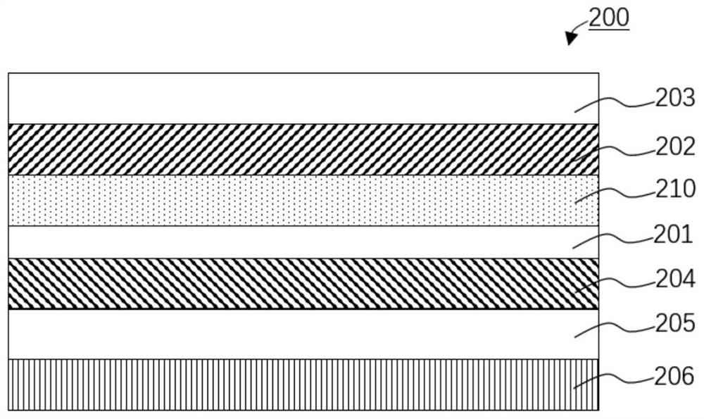
[0024] see figure 1 , the embodiment of the present application provides a polarizer 200, the polarizer 200 at least includes a polarizing functional layer 201 and a scattering layer 210, one side of the polarizing functional layer 201 is defined as the incident side of ambient light, then the opposite side of the polarizing functional layer 201 One side is defined as the display light incident side; wherein, the scattering layer 210 is located on the ambient light incident side of the polarizing functional layer 201 .
[0025] The scattering layer 210 includes an adhesive layer body, and scattering particles are disposed in the adhesive layer body.
[0026] The ambient light incident side of the polarizing functional layer 201 also includes a surface treatment layer 203 and a first protective layer 202, the scattering layer 210 is arranged on the polarizing functional layer 201, the first protective layer 202 is arranged on the scattering layer 210, and the surface treatment ...
Embodiment 2
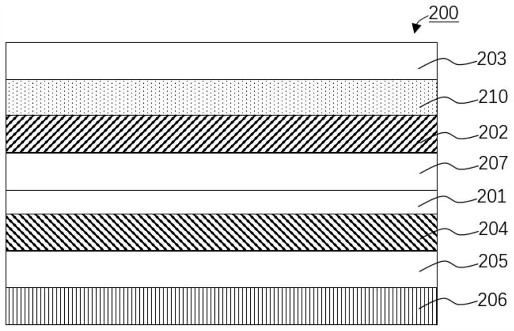
[0038] see figure 2 , the embodiment of the present application provides a polarizer 200, the polarizer 200 at least includes a polarizing functional layer 201 and a scattering layer 210, one side of the polarizing functional layer 201 is defined as the incident side of ambient light, then the opposite side of the polarizing functional layer 201 One side is defined as the display light incident side; wherein, the scattering layer 210 is located on the ambient light incident side of the polarizing functional layer 201 .
[0039] The scattering layer 210 includes an adhesive layer body, and scattering particles are disposed in the adhesive layer body.
[0040] The ambient light incident side of the polarizing functional layer 201 also includes a surface treatment layer 203, a first adhesive layer 207 and a first protective layer 202, the first adhesive layer 207 is arranged on the polarizing functional layer 201, and the first protective layer 202 is arranged On the first adhe...
Embodiment 3
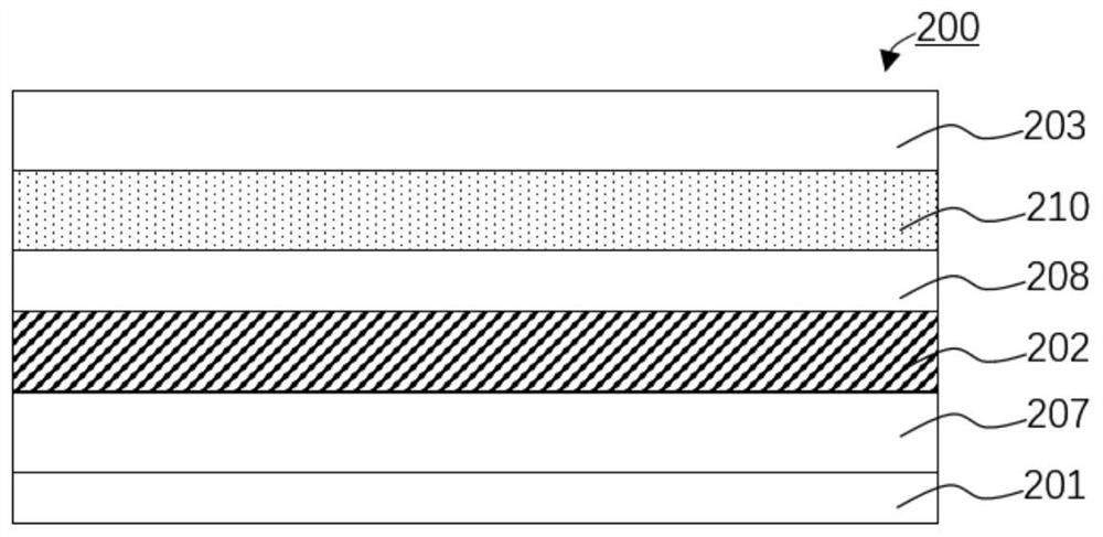
[0052] see image 3 , please combine Embodiment 1 and Embodiment 2. The difference between this embodiment and Embodiment 1 and Embodiment 201 is that the ambient light incident side of the polarizing functional layer 201 also includes other functional layers 208, and other functional layers 208 can be the third protection Layer, another surface treatment layer and other layers are not limited here.
[0053] exist image 3 It is shown that the other functional layer 208 is disposed on the first protective layer 202 , the scattering layer 210 is disposed on the other functional layer 208 , and the surface treatment layer 203 is disposed on the scattering layer 210 . Although the positions of the other functional layers 208 are exemplified, it is not limited thereto. For example, the other functional layers 208 may be disposed on the scattering layer 210 . Although the position of the scattering layer 210 has been illustrated, it is not limited thereto. For example, other func...
PUM
| Property | Measurement | Unit |
|---|---|---|
| particle diameter | aaaaa | aaaaa |
| refractive index | aaaaa | aaaaa |
| refractive index | aaaaa | aaaaa |
Abstract
Description
Claims
Application Information
 - R&D
- Intellectual Property
- Life Sciences
- Materials
- Tech Scout
- Unparalleled Data Quality
- Higher Quality Content
- 60% Fewer Hallucinations
Browse by: Latest US Patents, China's latest patents, Technical Efficacy Thesaurus, Application Domain, Technology Topic, Popular Technical Reports.
© 2025 PatSnap. All rights reserved.Legal|Privacy policy|Modern Slavery Act Transparency Statement|Sitemap|About US| Contact US: help@patsnap.com


