Optical component and timepiece

a technology applied in the field of optical components and timepieces, can solve the problems of poor productivity of optical components and high production costs, and achieve the effects of excellent appearance, high anti-reflection function, and large influence on the appearance of the entire timepi

Active Publication Date: 2017-02-28
SEIKO EPSON CORP
View PDF12 Cites 0 Cited by
  • Summary
  • Abstract
  • Description
  • Claims
  • Application Information

AI Technical Summary

Benefits of technology

[0018]The cover glass is present at a place close to the viewpoint of an observer (a user or the like) at the time of using a timepiece, and also time-displaying members such as a dial plate and hands are generally disposed on a rear surface side of the cover glass, and therefore, the cover glass (optical component) is a member which is strongly required to have visibility of a dial plate and the like through the cover glass (optical component). Therefore, in the case where the invention with which a high antireflection function is exhibited is applied to a cover glass, the effect of the invention is more remarkably exhibited.
[0019]Further, the cover glass is a component which has many opportunities to be visually recognized by an observer (a user or the like), and has a large influence on the appearance of the entire timepiece. In the aspect of the invention, a high antireflection function is exhibited, and therefore, the excellent appearance (aestheticity) inherent in an ornamental component such as a dial plate which is visually recognized through the cover glass can be effectively exhibited. Therefore, by applying the aspect of the invention to a cover glass for a timepiece, the aesthetic appearance of the timepiece as a whole can be made particularly excellent.
[0020]A timepiece according to an aspect of the invention includes the optical component according to the aspect of the invention.
[0021]According to this configuration, a timepiece capable of favorably visually recognizing a state on a rear surface side of the optical component can be provided, and the aesthetic appearance (aestheticity) of the timepiece as a whole can be made excellent, and thus, the value as an ornament can be increased. Further, for example, the visibility of the time and the like can be improved, and thus, also the function (practicality) as a utility article becomes excellent.
[0022]According to the aspects of the invention, an optical component including an antireflection film having a sufficient antireflection function with a simple structure can be provided, and also a timepiece including the optical component can be provided.

Problems solved by technology

Further, in the related art, each layer constituting an antireflection film is formed by a chemical vapor deposition, and therefore, the productivity of the optical component is poor, and also the production cost is high.

Method used


Image

  • Optical component and timepiece
  • Optical component and timepiece
  • Optical component and timepiece

Examples


first embodiment

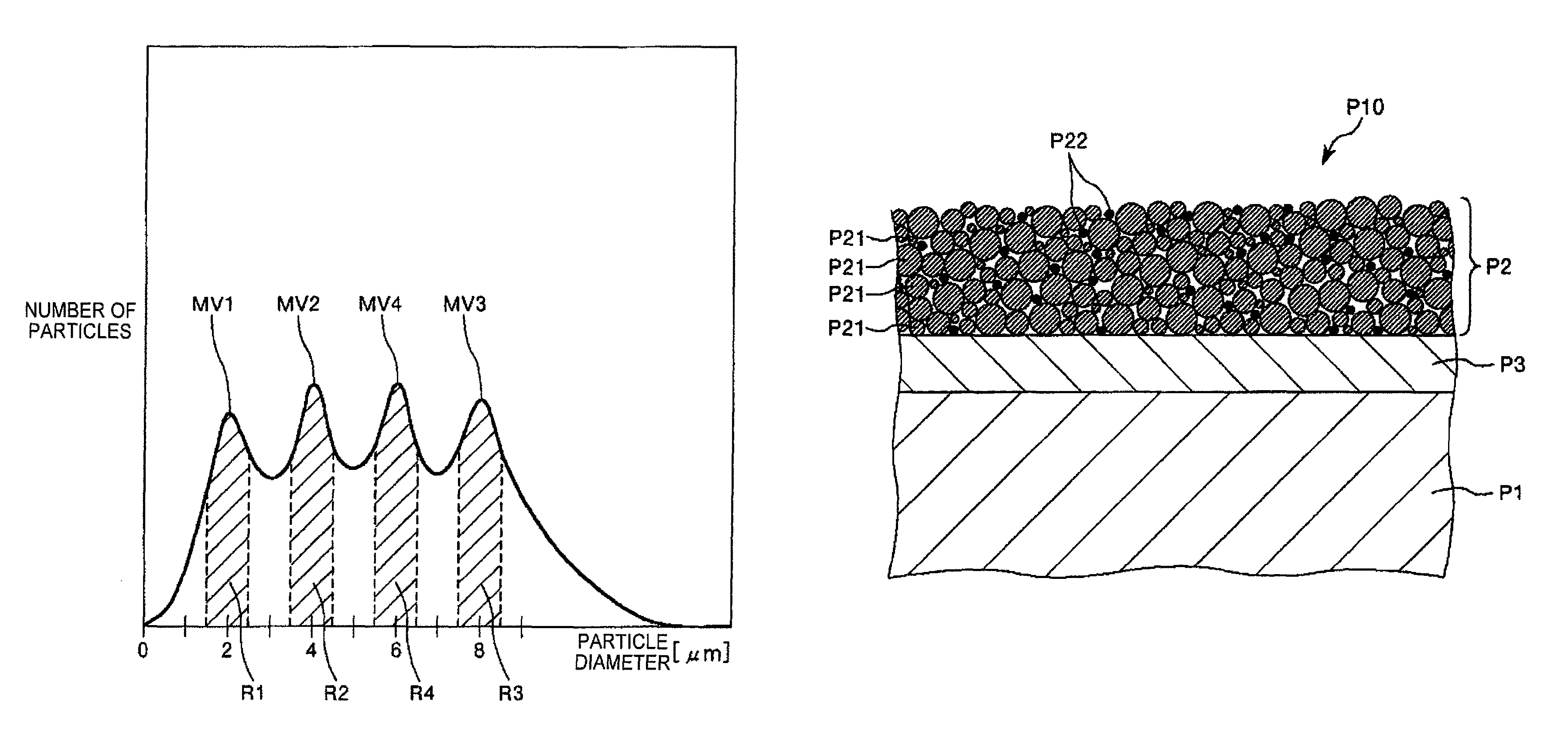
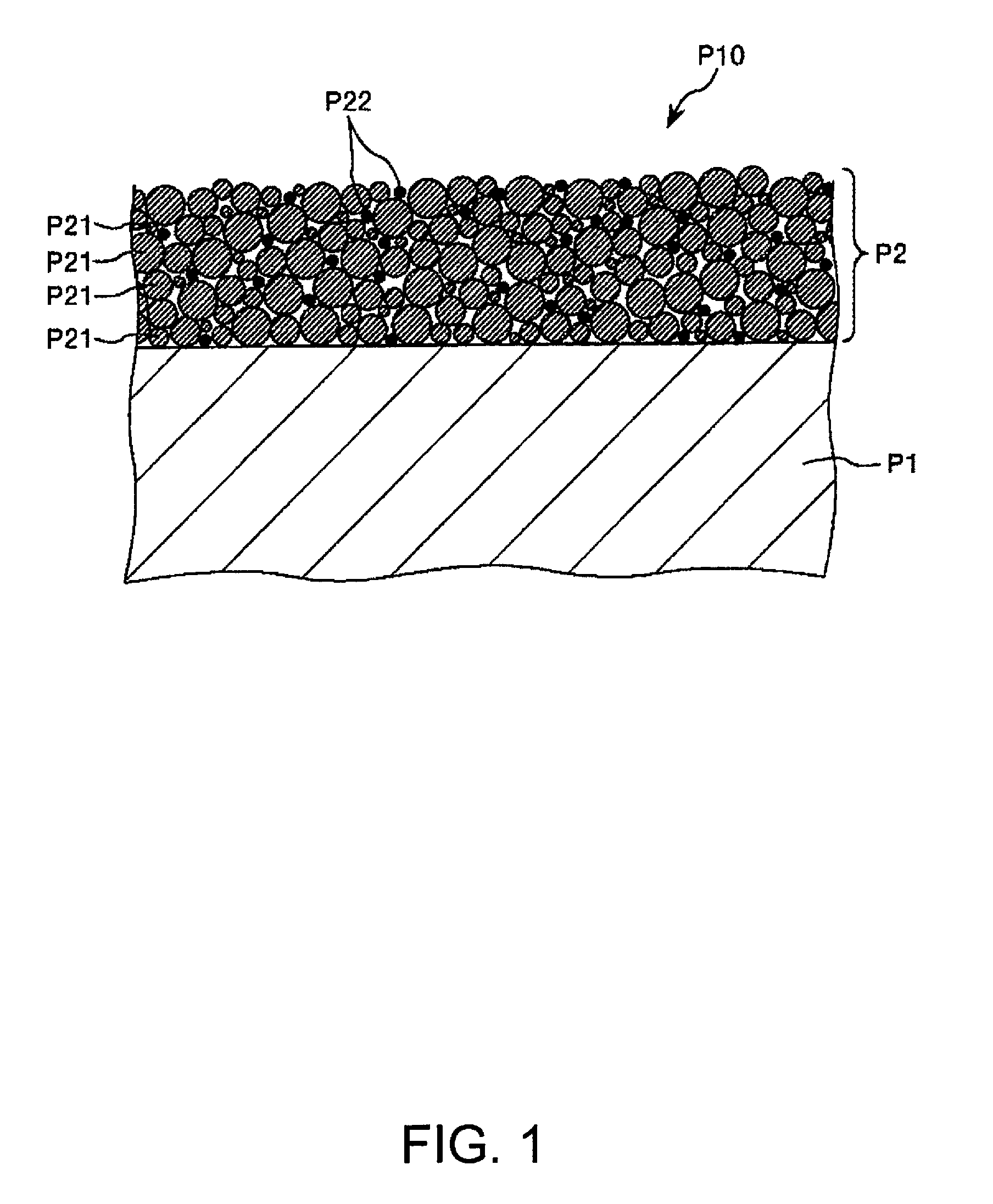
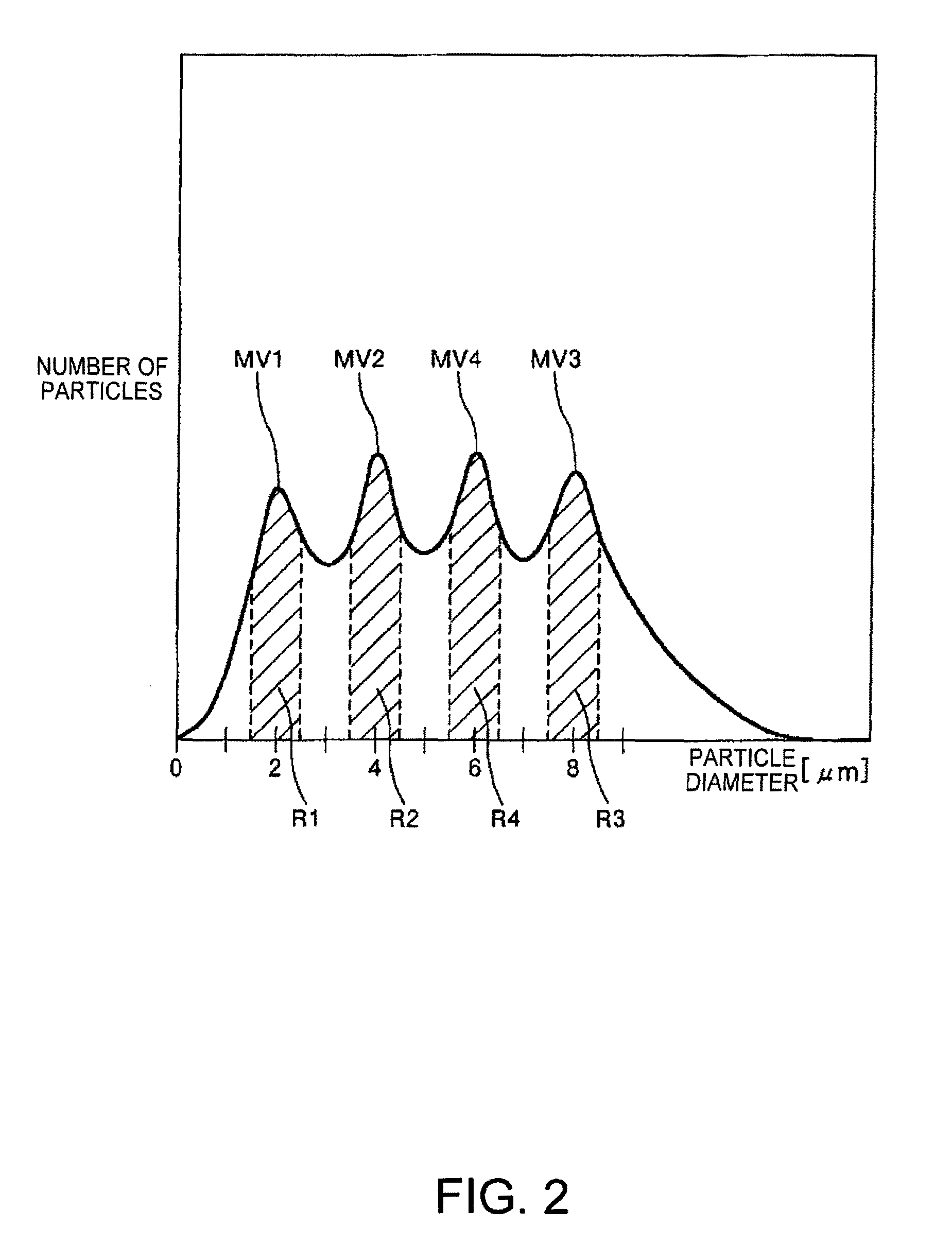
[0030]FIG. 1 is a cross-sectional view schematically showing a first embodiment of an optical component according to the invention, and FIG. 2 is a view schematically showing one example of a particle size distribution of silica particles constituting an antireflection film of an optical component according to the invention.

[0031]As shown in FIG. 1, an optical component P10 of this embodiment includes a base material P1 and an antireflection film P2 containing silica particles P21.

[0032]The porosity of the antireflection film P2 is 15% by volume or more and 36% by volume or less.

[0033]Since the antireflection film P2 has such a porosity, an excellent antireflection function is obtained while making the mechanical strength of the antireflection film P2 sufficiently excellent. In particular, with a very simple structure as compared with an antireflection film in the related art, an excellent antireflection function is obtained. Due to this, the optical component P10 can stably exhibit...

second embodiment

[0114]FIG. 3 is a cross-sectional view schematically showing a second embodiment of the optical component according to the invention. In the following description, different points from the above embodiment will be mainly described, and the description of the same matter will be omitted.

[0115]As shown in FIG. 3, an optical component P10 of this embodiment includes a base material P1, an antireflection film P2 containing silica particles P21, and a foundation layer P3.

[0116]In this manner, by including the foundation layer P3, for example, the adhesiveness between the base material P1 and the antireflection film P2 (the adhesiveness through the foundation layer P3) can be made particularly excellent, and thus, the durability and reliability of the optical component P10 can be made particularly excellent.

[0117]Examples of a constituent material of the foundation layer P3 include various resin materials and SiO2.

[0118]The thickness of the foundation layer P3 is not particularly limited...

example 1

[0184]By the method as described below, a cover glass as an optical component was produced.

[0185]First, a plate material (glass plate) composed of a sapphire glass was prepared as a base material (the base material preparation step), and a necessary part was cut and polished. The base material obtained by cutting and polishing had a substantially disk shape and had a size of 30 mm in diameter and 1 mm in thickness.

[0186]Subsequently, a UV irradiation treatment in which an ultraviolet ray with a wavelength of 248 nm was irradiated on the surface of the base material on the side where an antireflection film was going to be formed.

[0187]Subsequently, an antireflection film forming composition was applied onto the entire surface of one side of the base material by a spray coating method (antireflection film forming composition application step).

[0188]As the antireflection film forming composition, a composition obtained by mixing silica particles, tin oxide (SnO2) particles (number-base...


PUM

PropertyMeasurementUnit
number-based average particle diameteraaaaaaaaaa
particle diameteraaaaaaaaaa

Abstract

An optical component includes a base material and an antireflection film containing silica particles, wherein the porosity of the antireflection film is 15% by volume or more and 36% by volume or less. The number-based average particle diameter of the silica particles is preferably 0.5 nm or more and 4.0 nm or less. The antireflection film is preferably formed by using a composition containing the silica particles and a dispersion medium for dispersing the silica particles. The thickness of the antireflection film is preferably 50 nm or more and 120 nm or less.

Description

BACKGROUND[0001]1. Technical Field[0002]The present invention relates to an optical component and a timepiece.[0003]2. Related Art[0004]In an optical component such as a cover glass for a timepiece, an antireflection film which prevents light reflection is provided for the purpose of enhancing visibility on an opposite surface side or the like.[0005]In the related art, an optical component had a complicated structure such that many layers are stacked on one another for obtaining a sufficient antireflection function (see, for example JP-A-2010-37115). Further, in the related art, each layer constituting an antireflection film is formed by a chemical vapor deposition, and therefore, the productivity of the optical component is poor, and also the production cost is high.SUMMARY[0006]An advantage of some aspects of the invention is to provide an optical component including an antireflection film having an excellent antireflection function with a simple structure, and also to provide a t...

Claims


Application Information

Patent Timeline
Patent Type & Authority Patents(United States)
IPC IPC(8): G02B1/11G02B1/18G04B39/00
CPCG02B1/11G02B1/18G04B39/002G04B39/004
Inventor FURUSATO, DAIKISUZUKI, KATSUMI
Owner SEIKO EPSON CORP
Why Eureka
Try Eureka