Electric motor control apparatus

a control apparatus and motor technology, applied in the direction of motor/generator/converter stopper, dynamo-electric converter control, polyphase induction motor starter, etc., can solve the problem of affecting the effect of electric motor by erroneously learning the offset correction value, and deteriorating current detection accuracy

Active Publication Date: 2011-03-31
MITSUBISHI ELECTRIC CORP
View PDF8 Cites 13 Cited by
  • Summary
  • Abstract
  • Description
  • Claims
  • Application Information

AI Technical Summary

Benefits of technology

[0007]In the current detection circuit described in JP-A-3-186477, correction of an offset at the time when an electric motor is not driven can be made as described above. However, a deviation of an offset occurring depending on temperature characteristics of a circuit element in a state of driving the electric motor cannot be corrected. On the other hand, in the current detection apparatus described in JP-A-10-132869, an offset occurring depending on temperature characteristics and characteristic variations in a circuit element constituting current detection means can be corrected in real time. However, since both the offsets occurring depending on temperature characteristics and characteristic variations in the circuit element are corrected in real time, a possible value of an offset correction value becomes large, and, for example, when noise is superimposed on a waveform of a voltage across a shunt resistor at the time of turning off a switching element by a switching operation of a bridge circuit at the time of driving an electric motor, updating of a large amount of deviation including this noise as the offset correction value is permitted, which results in the deterioration of current detection accuracy. Therefore, an influence on the electric motor by erroneously learning the offset correction value becomes large.
[0008]Also, the offset correction value is stored in memory and when the memory is damaged, the offset correction value stored in the memory becomes indefinite and becomes an unreliable value, so that a correction value has to be set at 0 when abnormality is detected in the offset correction value. Since a possible value of the offset correction value is large as described above, a change range of the offset correction value is large before and after damage to the memory and current detection accuracy deteriorates greatly, so that there was also a problem that an influence on the electric motor at the time of damage to the memory is also large.
[0009]The invention was made in view of the above circumstances, and an object of the invention is to provide an electric motor control apparatus capable of reducing an influence on an electric motor in the case of erroneously learning an offset correction value and correcting an offset occurring depending on temperature characteristics in real time while correcting an offset occurring depending on characteristic variations in a circuit element constituting current detection means.
[0010]According to an aspect of the invention, there is provided an electric motor control apparatus comprising: an electric motor; an electric motor driving unit configured to drive the electric motor; and a control unit configured to control the electric motor driving unit, wherein the electric motor driving unit comprises: a current detection unit configured to detect a current flowing through a current detection place provided in the electric motor driving unit, wherein the control unit comprises a current calculation unit configured to calculate a current value of a current flowing through the electric motor from an offset correction value obtained based on a first detection value detected at a time when a current flows through the current detection place and a second detection value detected at a time when a current does not flow through the current detection place, and wherein the offset correction value includes: a first offset correction value stored in nonvolatile memory of the control unit at a time of assembling the electric motor control apparatus; and a second offset correction value computed by the control unit while the electric motor is driven.

Problems solved by technology

However, a deviation of an offset occurring depending on temperature characteristics of a circuit element in a state of driving the electric motor cannot be corrected.
However, since both the offsets occurring depending on temperature characteristics and characteristic variations in the circuit element are corrected in real time, a possible value of an offset correction value becomes large, and, for example, when noise is superimposed on a waveform of a voltage across a shunt resistor at the time of turning off a switching element by a switching operation of a bridge circuit at the time of driving an electric motor, updating of a large amount of deviation including this noise as the offset correction value is permitted, which results in the deterioration of current detection accuracy.
Therefore, an influence on the electric motor by erroneously learning the offset correction value becomes large.
Also, the offset correction value is stored in memory and when the memory is damaged, the offset correction value stored in the memory becomes indefinite and becomes an unreliable value, so that a correction value has to be set at 0 when abnormality is detected in the offset correction value.
Since a possible value of the offset correction value is large as described above, a change range of the offset correction value is large before and after damage to the memory and current detection accuracy deteriorates greatly, so that there was also a problem that an influence on the electric motor at the time of damage to the memory is also large.

Method used


Image

  • Electric motor control apparatus
  • Electric motor control apparatus
  • Electric motor control apparatus

Examples


first embodiment

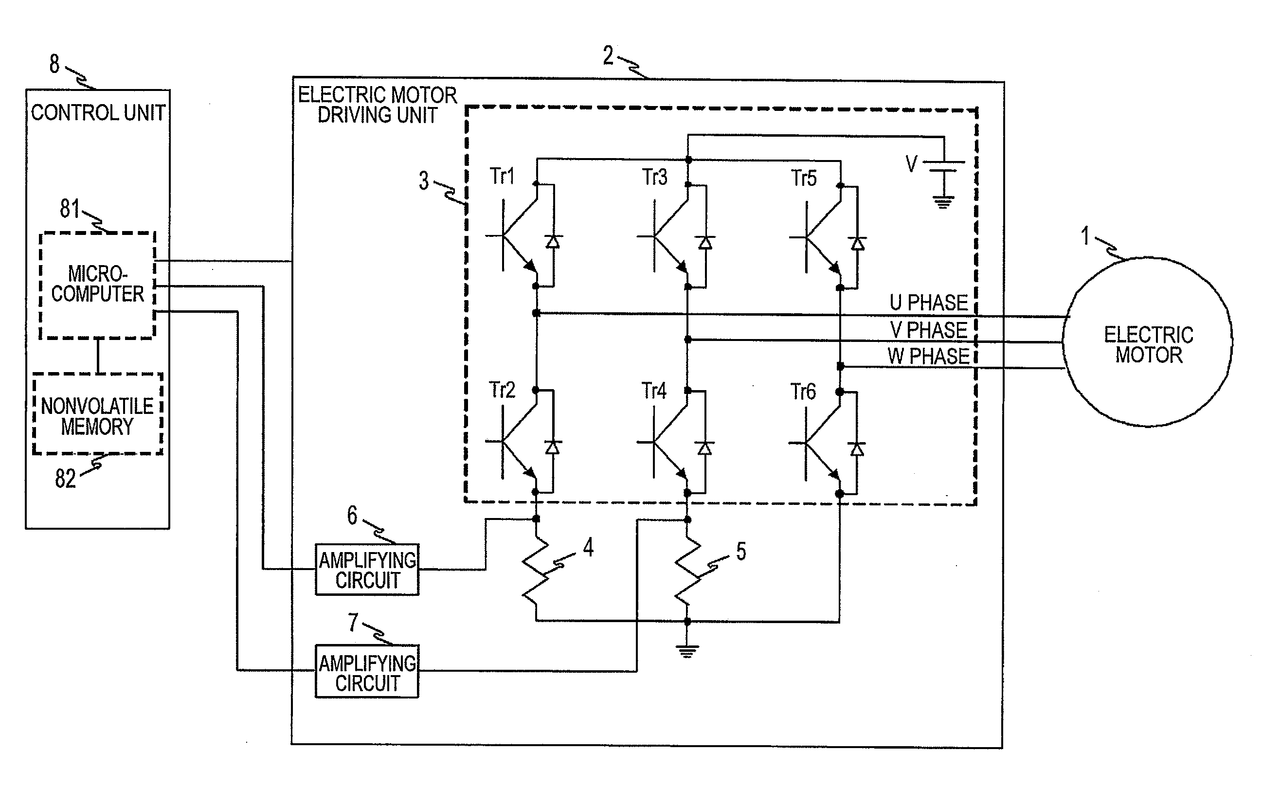
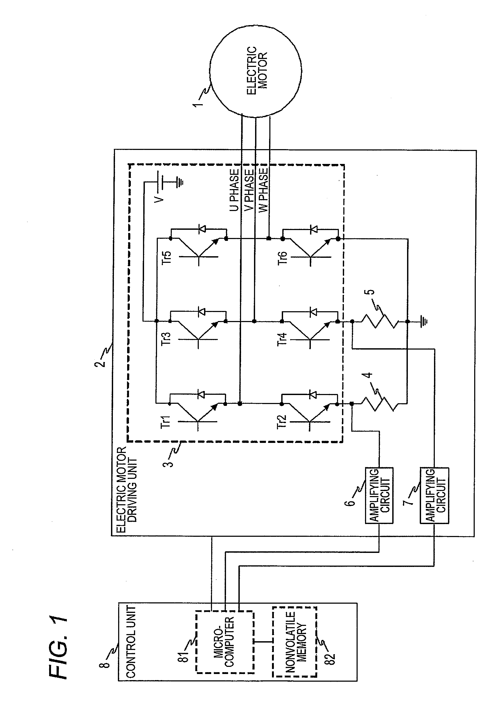
[0020]FIG. 1 is a block diagram showing a configuration of an electric motor control apparatus according to a first embodiment of the invention. In FIG. 1, an electric motor driving unit 2 for driving an electric motor 1 which is a three-phase motor includes: a bridge circuit 3 including six switching elements Tr1 to Tr6, resistors 4, 5 connected in series between GND and the switching elements Tr2, Tr4 which are connected on low potential sides of two of switching element groups of this bridge circuit 3; and amplifying circuits 6, 7 for amplifying voltages across the resistors 4, 5, respectively. A control unit 8 configured to control the electric motor driving unit 2 includes: a microcomputer 81 for incorporating an A / D converter etc. for digitizing and detecting the voltages across resistors after amplification outputted from the amplifying circuits 6, 7; and nonvolatile memory 82 configured to store various information such as an offset correction value. The control unit 8 perfo...

second embodiment

[0046]FIG. 5 shows one example of a waveform detected in a resistor 4 in the electric motor control apparatus shown in FIG. 1, and the axis of abscissa shows time and the axis of ordinate shows a current detection value. Also, FIG. 5A shows the case where an on-duty value is small, and FIG. 5B shows the case where the on-duty value is large. Here, the on-duty value is a value indicating a percentage of an on interval among a PWM control signal and, for example, the value is 0% when a percentage of the on interval is 0, and is 50% when a percentage of the on interval is equal to a percentage of an off interval, and a percentage of the off interval becomes small as the on-duty value is large. In the electric motor control apparatus having the electric motor driving unit for driving the electric motor by PWM control shown in the first embodiment, for example, when the on-duty value which is a percentage of the on interval of the PWM control signal is small as shown in FIG. 5A, a detect...

third embodiment

[0051]FIG. 7 is a flowchart showing an operation of an electric motor control apparatus according to a third embodiment of the invention. In addition, a block diagram of the electric motor control apparatus according to the third embodiment of the invention is the same as that of FIG. 1 and a configuration of an offset correction value is the same as that of the first embodiment, so that its detailed description is omitted. In FIG. 7, processing for determining whether or not the number of rotations of an electric motor is a predetermined value (N) or more is performed in S50. Here, the number of rotations of the electric motor is a value calculated from a value etc. detected from a rotational angle sensor. When the electric motor rotates, back electromotive force is generated and as a rotational speed increases, more back electromotive force is generated, so that it is necessary to increase an on-duty value of a pulse width modulation signal and increase a voltage applied to the el...


PUM


Abstract

In an electric motor control apparatus, an electric motor driving unit includes: a current detection unit configured to detect a current flowing through a current detection place in the electric motor driving unit. A control unit includes a current calculation unit configured to calculate a current value of a current flowing through an electric motor from an offset correction value obtained based on a first detection value detected at a time when a current flows through the current detection place and a second detection value detected at a time when a current does not flow through the current detection place. The offset correction value includes: a first offset correction value stored in nonvolatile memory of the control unit at a time of assembling the electric motor control apparatus; and a second offset correction value computed by the control unit while the electric motor is driven.

Description

CROSS-REFERENCE TO RELATED APPLICATIONS[0001]This application claims priority from Japanese Patent Application No. 2009-222555 filed on Sep. 28, 2009, the entire contents of which are incorporated herein by reference.BACKGROUND OF THE INVENTION[0002]1. Field of the Invention[0003]The present invention relates to an electric motor control apparatus, and particularly to an electric motor control apparatus for controlling an electric motor so as to improve current detection accuracy.[0004]2. Description of Related Art[0005]Conventionally, in current detection of an electric motor, a current detection resistor such as a shunt resistor is connected in series with the electric motor and the current detection is performed based on a voltage occurring across this current detection resistor. As means for correcting an offset occurring by characteristic variations in a circuit element constituting this current detection means, a current detection circuit described in JP-A-3-186477 is proposed...

Claims


Application Information

Patent Timeline
Patent Type & Authority Applications(United States)
IPC IPC(8): H02P23/14H02P23/07H02P27/08
CPCH02M7/53873H02M2001/0009H02P27/08H02M1/0009
Inventor MATSUSHITA, MASAKIKIFUKU, TAKAYUKIHORI, YASUAKI
Owner MITSUBISHI ELECTRIC CORP
Why Eureka
Try Eureka