Optical recording condition setting method, optical recording/reproducing device, control program, and recording medium

a technology of optical recording and condition setting, which is applied in the direction of digital signal error detection/correction, instruments, recording signal processing, etc., can solve the problems of uneven properties of the respective optical disk recording/reproducing device, uneven formation of record-marks on the respective optical disks, etc., to improve the quality of reproduced signals, shorten the length of record-marks, and improve the effect of reproduction quality

Inactive Publication Date: 2005-08-04
SHARP KK
View PDF40 Cites 12 Cited by
  • Summary
  • Abstract
  • Description
  • Claims
  • Application Information

AI Technical Summary

Benefits of technology

[0015] In the foregoing invention, the shortest-mark-recording-power parameter for use in forming the shortest record-mark is varied, in order to determine the recording-power parameters for improving the quality of the reproduced signals.
[0016] More specifically, shorter the length of the record-mark is, less a number of the recording-power parameters to be varied becomes, as such, it becomes difficult to set the recording-power parameters that result in the good quality of the reproduced signals. Further, shorter the length of the record mark is, more frequently the record mark appears within a data set, therefore the record-mark having a shorter length has a larger influence to an overall quality of forming the record marks. This requires that recording-power parameter for use in forming the shorter record-mark be more delicately adjusted. Accordingly, the quality of the overall reproduced signals is most effectively improved by selecting the shortest-mark-recording-power parameter under which the good quality of the reproduced signal is obtained, the shortest-mark-recording-power parameter for use in forming the shortest record-mark.
[0017] As a result it is possible to provide (i) a method for setting the optical recording conditions, in which effects from uneven properties of a rewritable or recordable optical disk and an optical recording / reproducing device are reduced, and (ii) an optical recording / reproducing device which executes the method.

Problems solved by technology

However, due to changes in environment and uneven properties of parts being used, properties of each of mass-produced optical disk recording / reproducing devices are not always the same.
Similarly, properties of the respective optical disks being mass-produced may be uneven.
This may cause uneven formation of the record-mark on the respective optical disks even if the record-mark is formed under uniform recording conditions.
Accordingly, some combinations of the mass-produced optical disk and the mass-produced optical disk recording / reproducing device being used as they are may not carry out appropriate recording, and may result in defective quality, even in a case where properties of the optical disk are standard, and the standard recording conditions are set by using the optical disk recording / reproducing device having the standard properties.
However, in a case where properties for forming the record-mark are different depending on the record-mark length, a predetermined change uniformly added may not result in appropriate formnations of the record-marks of the respective record-mark lengths.
This resulted in an insufficient improvement in the quality of the reproduced signals reproduced from the overall spaces and the record marks.

Method used


Image

  • Optical recording condition setting method, optical recording/reproducing device, control program, and recording medium
  • Optical recording condition setting method, optical recording/reproducing device, control program, and recording medium
  • Optical recording condition setting method, optical recording/reproducing device, control program, and recording medium

Examples


embodiment 1

[Embodiment 1]

[0035] The following describes an embodiment of the present invention, with reference to FIGS. 1 to 6.

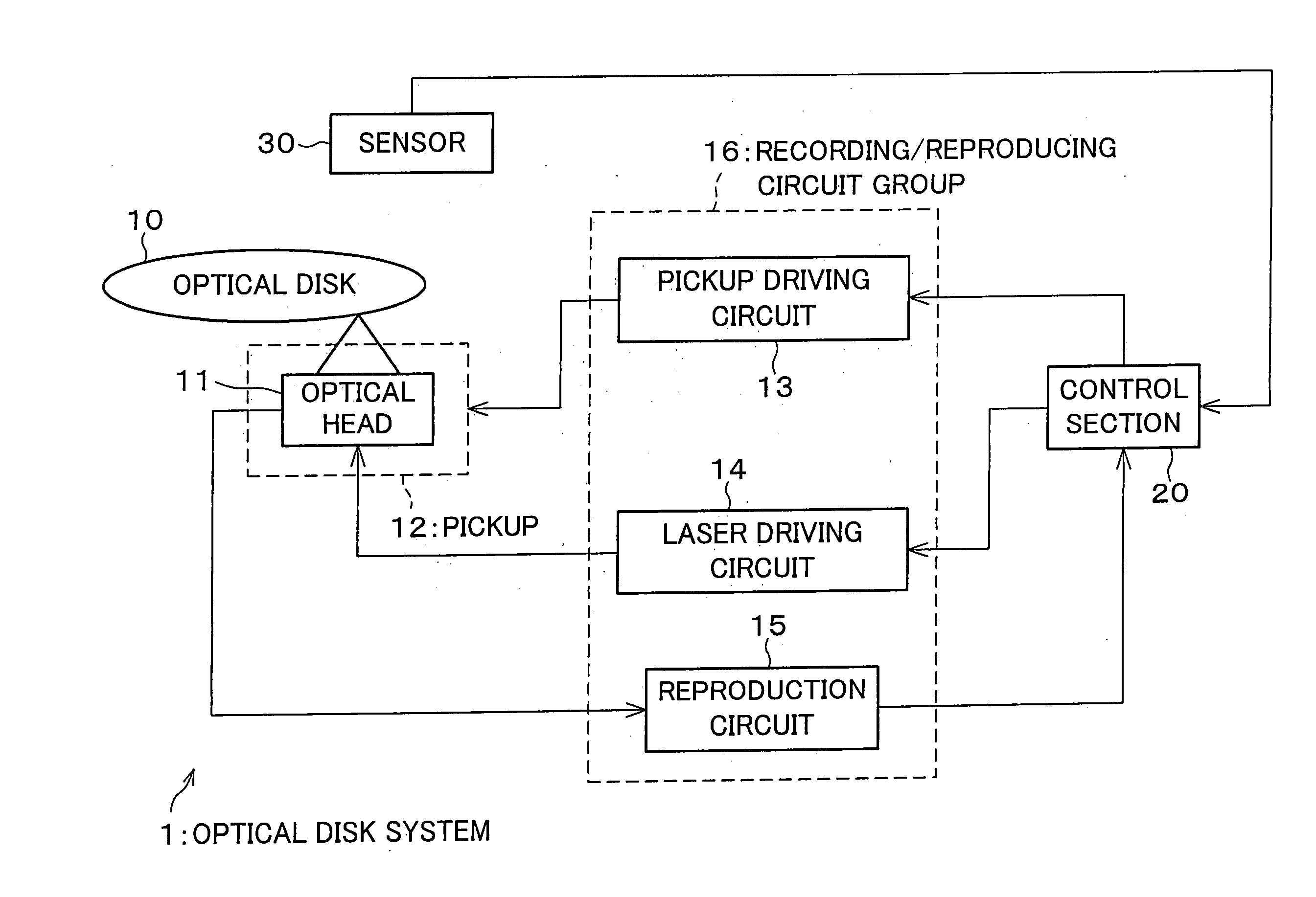
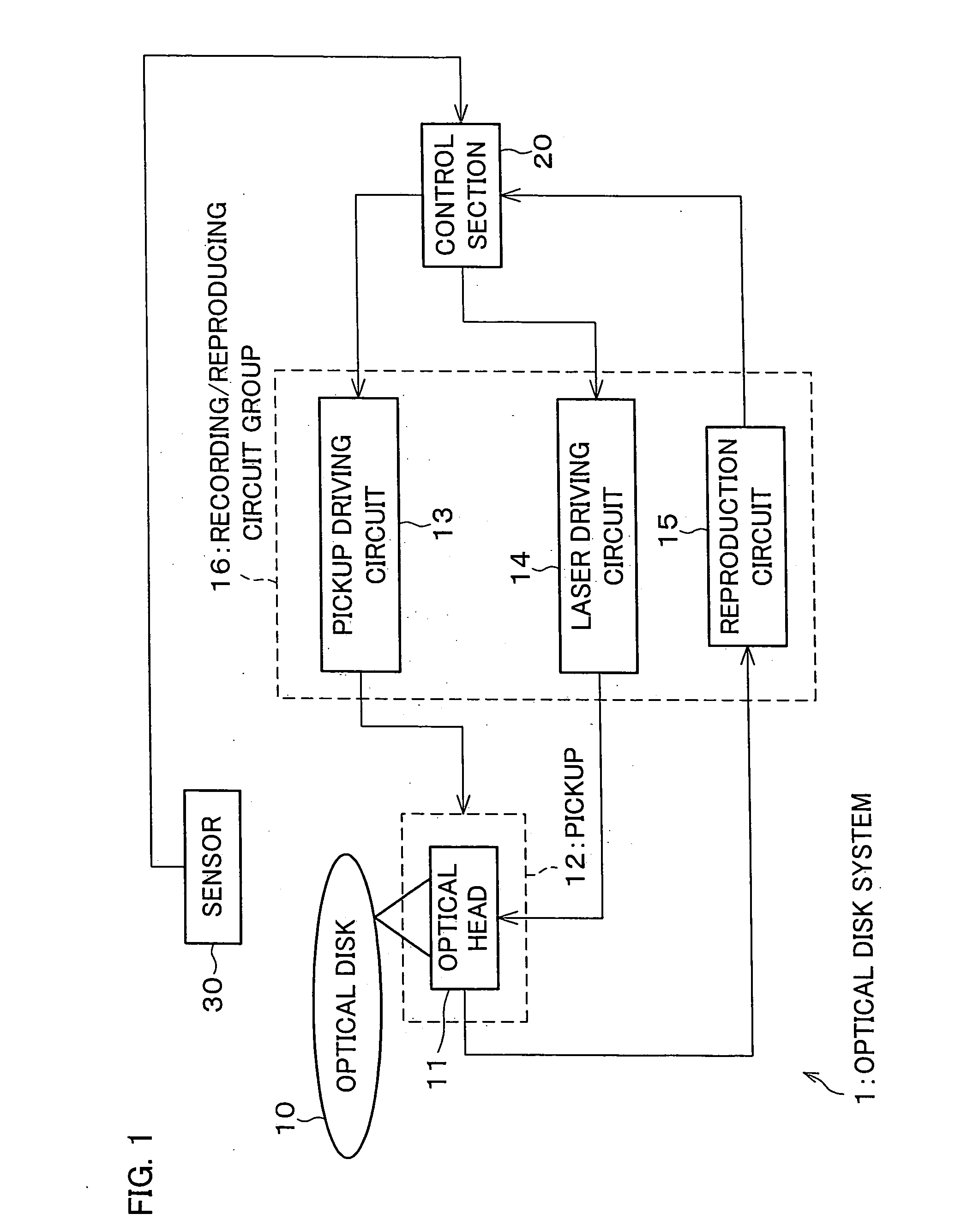
[0036] As shown in FIG. 1, in an optical disk system 1 serving as an optical recording / reproducing device to which an optical recording condition setting method of the present invention is adopted, a control section (reproduced-signal-evaluating means, recording-power determining means, recording-pulse determining means) 20 causes a pickup driving circuit 13 to move a pickup (reproduced-signal-evaluating means) 12 to a track (not shown) of a spinning optical disk 10.

[0037] The pickup 12 is provided with an optical head 11. The recording conditions are set by the control section 20 through a laser driving circuit (laser driver, first test writing means, second test writing means) 14. From the optical head 11, a laser beam for use in recording is irradiated to a record-site of the optical disk 10, so that information is recorded on the track of the optical disk 10.

[00...

embodiment 2

[Embodiment 2]

[0067] The following describes another embodiment in accordance with the present invention, with reference to FIG. 7. It should be noted that features of the present embodiment are the same as those of the foregoing embodiment 1, unless otherwise described hereinbelow. Accordingly, the same symbols are given to the members that have the same functions as those shown in Figures of the foregoing embodiment 1, and are the descriptions of those members omitted here as a matter of convenience.

[0068] In an optical recording condition setting method of the present embodiment, a number of writing pulse conditions to be set increases as a length of record-mark increases.

[0069] More specifically, as described, shorter the length of the record-mark is, less a number of recording-power parameters to be varied becomes, therefore it becomes more difficult to set the writing pulse conditions to realize a good quality of reproduced signals reproduced from the record-mark having a sh...

embodiment 3

[Embodiment 3]

[0082] The following describes another embodiment in accordance with the present embodiment, with reference to FIG. 8. It should be noted that features of the present embodiment are the same as those of the foregoing embodiments 1 and 2, unless otherwise described hereinbelow. Accordingly, the same symbols are given to the members that have the same functions as those shown in Figures of the foregoing embodiments 1 and 2, and are the descriptions of those members omitted here as a matter of convenience.

[0083] In an optical recording condition setting method of the present invention, test writing is carried out so that recording-power parameters are appropriately set for each of record-mark lengths, prior to carrying out setting of the recording-power parameters with respect to each of the record-mark lengths. This allows more accurate setting of recording-power parameters.

[0084] Further, in the present embodiment, in order to determine the appropriate recording-power...


PUM

PropertyMeasurementUnit
recording-power parameteraaaaaaaaaa
poweraaaaaaaaaa
lengthaaaaaaaaaa

Abstract

In order to provide an optical recording condition setting method which reduces effects from uneven properties of a rewritable or recordable optical disk and an optical recording/reproducing device, and to provide an optical recording/reproducing device which executes the method, (i) a test writing is carried out with respect to an optical disk under various settings of recording-power parameters for use in forming a shortest record-mark (S1 to S3), (iii) a test pattern used in the test writing is reproduced (S4), and then (iv) recording-power parameters that result in a good quality of reproduced signals are selected (S5).

Description

[0001] This Nonprovisional application claims priority under 35 U.S.C. § 119(a) on Patent Application No. 24733 / 2004 filed in Japan on Jan. 30, 2004, the entire contents of which are hereby incorporated by reference.FIELD OF THE INVENTION [0002] The present invention relates to optical recording condition setting method and a control program therefor, in which (I) recording conditions are set by (i) reading out setting information for determining recording conditions stored in a specific region of the optical medium such as an optical disk, or (ii) outputting the setting information from inside of a device, and (II) the recording conditions are corrected by recording and reproducing under the recording conditions in a specific region for use in determining the recording conditions. The present invention also relates to an optical recording / reproducing device and a recording medium each of which storing therein the control program. BACKGROUND OF THE INVENTION [0003] Mass storage opti...

Claims


Application Information

Patent Timeline
Patent Type & Authority Applications(United States)
IPC IPC(8): G11B7/0045G11B5/09G11B7/00G11B7/006G11B7/007G11B7/125G11B7/1267G11B27/36
CPCG11B7/0062G11B7/00736G11B7/1267G11B2220/2575G11B2220/216G11B2220/218G11B2220/2562G11B27/36
Inventor ADACHI, YOSHIHISAMAEDA, SHIGEMI
Owner SHARP KK
Why Eureka
Try Eureka