

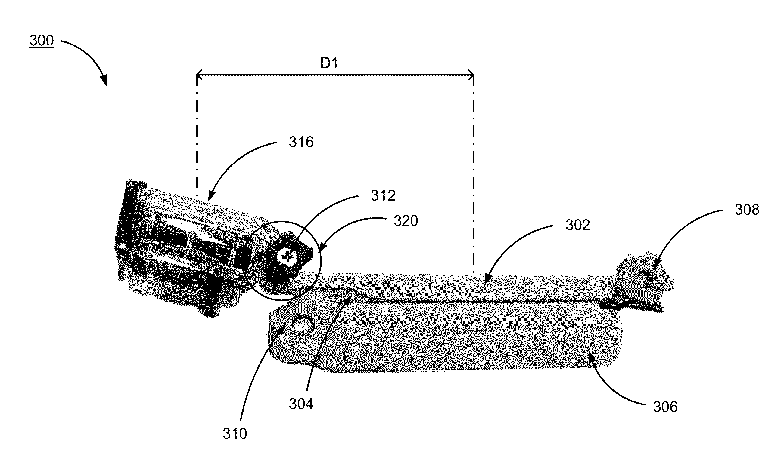
Camera mountable arm
a technology of a camera and a mounting bracket, which is applied in the field of camera systems, can solve the problems of limited user maneuverability in handling the camera, limited camera field of view, and limited user maneuverability
- Summary
- Abstract
- Description
- Claims
- Application Information
AI Technical Summary
Benefits of technology
Problems solved by technology
Method used
Image

Examples
example camera
System Configuration
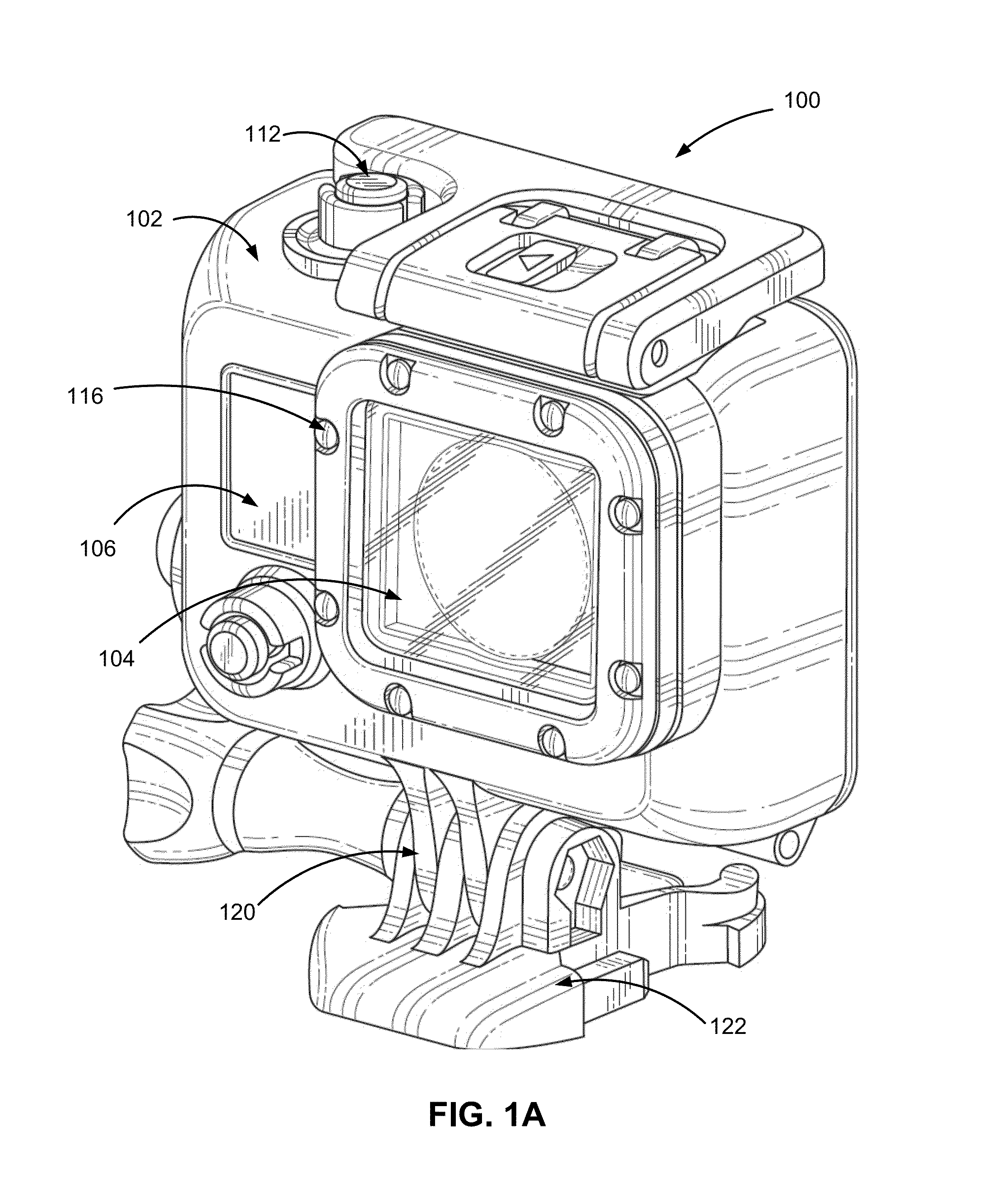
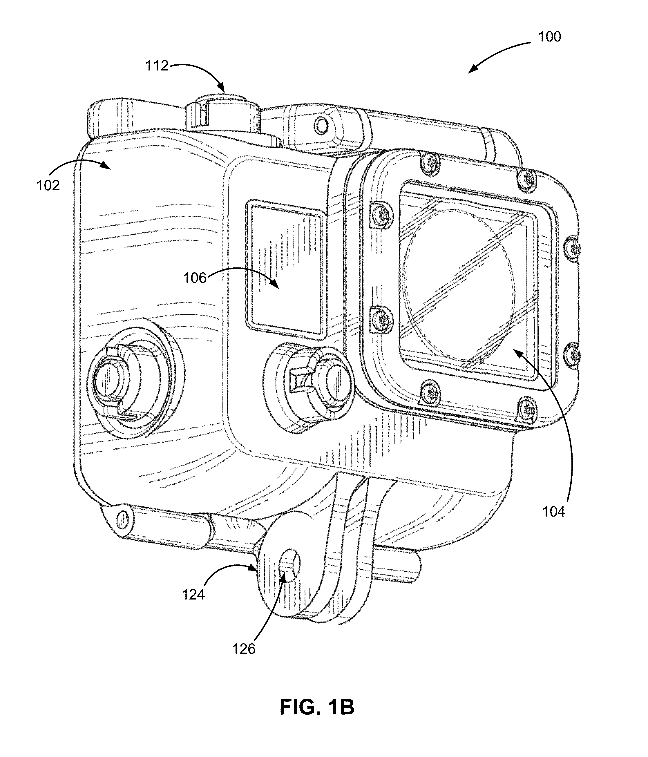
[0017]A camera system includes a camera and a camera housing structured to at least partially enclose the camera. The camera comprises a camera body having a camera lens structured on a front surface of the camera body, various indicators on the front of the surface of the camera body (such as LEDs, displays, and the like), various input mechanisms (such as buttons, switches, and touch-screen mechanisms), and electronics (e.g., imaging electronics, power electronics, etc.) internal to the camera body for capturing images via the camera lens and / or performing other functions. The camera housing includes a lens window structured on the front surface of the camera housing and configured to substantially align with the camera lens, and one or more indicator windows structured on the front surface of the camera housing and configured to substantially align with the camera indicators.
[0018]FIGS. 1a and 1b illustrate various views of a camera system according to one exa...
PUM
 Abstract
Description
Claims
Application Information