Intrauterine contraceptive device

a contraceptive device and intrauterine technology, applied in the field of medical devices, can solve the problems of abnormal bleeding and pain, many currently available iuds are at least slightly uncomfortable and/or difficult to deliver into the uterus, and both have common side effects, so as to facilitate the delivery of an iud, reduce the migration and expulsion of inferiors, and facilitate the effect of delivering an iud

Active Publication Date: 2015-07-28
SEBELA VLC LTD
View PDF13 Cites 11 Cited by
  • Summary
  • Abstract
  • Description
  • Claims
  • Application Information

AI Technical Summary

Benefits of technology

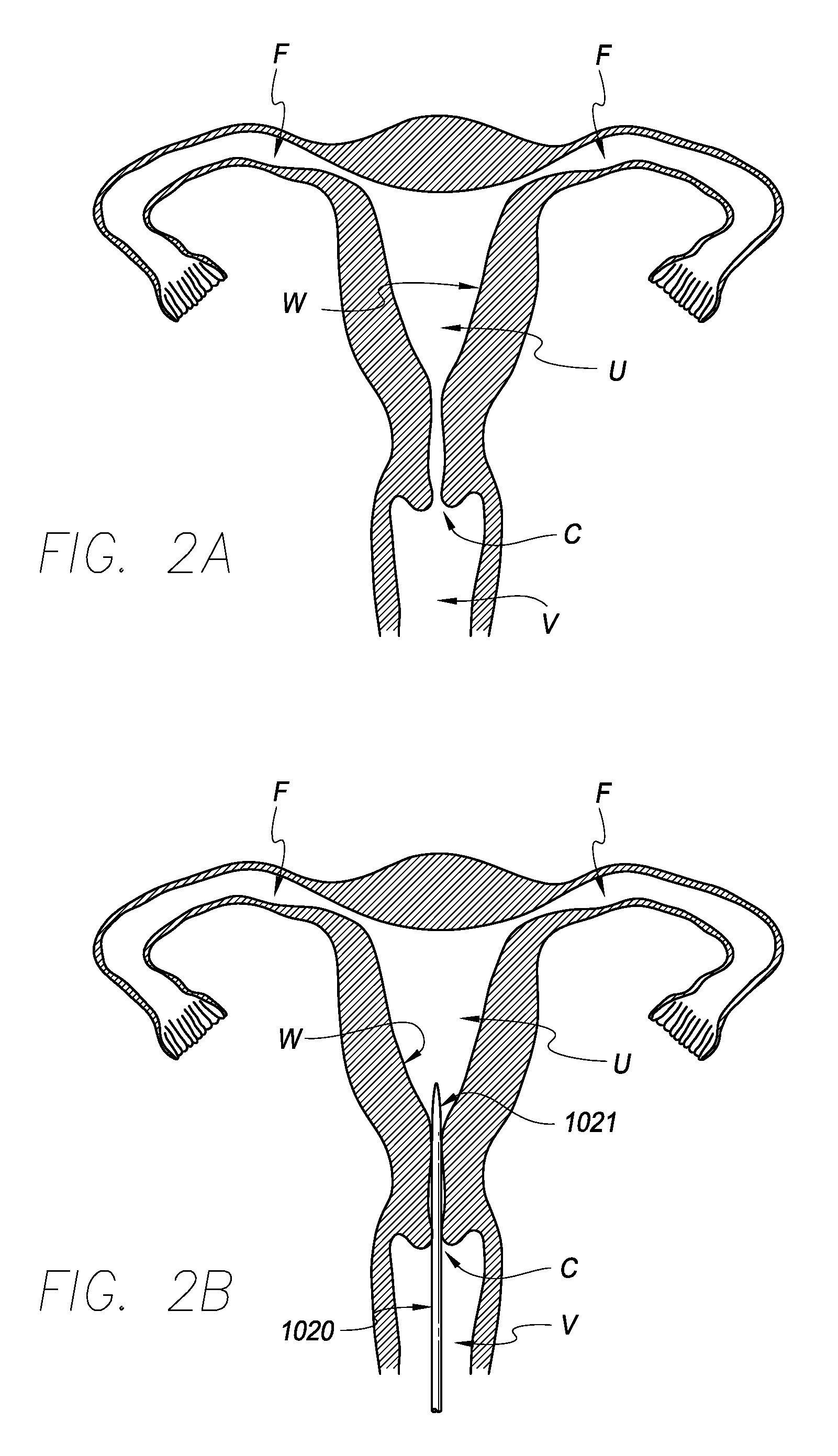
[0012]In one aspect, a method for promoting contraception by placing a contraceptive device within a uterus without blocking fallopian tubes may include advancing a distal end of a delivery device through a cervix, advancing the contraceptive device comprising an elongate shape memory member out of the distal end of the delivery device and into the uterus, and limiting inferior migration of the contraceptive device within the uterus. Advancing the contraceptive device out of the distal end of the delivery device may cause the device to expand from a first, compressed shape within the delivery device to a second, expanded shape within the uterus. In the expanded shape, two tissue contact surfaces at opposite ends of the shape memory member may contact the inner wall of the uterus, and each of the tissue contact members, when the contraceptive device is delivered, may be positioned near, but not within, an opening of one of the two fallopian tubes branching from the uterus. Inferior migration may be limited by allowing the contraceptive device to assume a third shape, when subjected to pressure that tends to cause a downward migration of the device within the uterus, in which the tissue contact members are closer together than in the second shape and in which an expandable middle portion of the device is expanded to contact the inner wall of the uterus and thus limit the downward migration of the device.
[0014]In some embodiments, the method may further include removing the contraceptive device through the cervix by pulling on a thread connected to the contraceptive device. In some embodiments, the distal end of the delivery device may be tapered, and the contraceptive device may be completely contained within the delivery device during advancement of the delivery device through the cervix. In some embodiments, advancing the contraceptive device out of the delivery device may involve delivering the contraceptive device to a first, inferior location in the uterus, and the method may further include allowing the contraceptive device to migrate superiorly to a second location in the uterus after delivery. In some embodiments, the method may further involve applying sufficient pressure against the wall of the uterus with the tissue contact surfaces to promote contraception.
[0016]In some embodiments, the method may also involve, before delivering the substance, advancing a distal end of a delivery device through a cervix, and advancing the contraceptive device comprising an elongate shape memory member out of the distal end of the delivery device and into the uterus, thus causing the contraceptive device to expand from a first, compressed shape within the delivery device to a second, expanded shape within the uterus, where two tissue contact surfaces at opposite ends of the shape memory member contact the inner wall of the uterus when the contraceptive device is in the second shape, and where each of the tissue contact members, when the contraceptive device is delivered, is positioned near, but not within, an opening of one of the two fallopian tubes branching from the uterus.
[0017]In some embodiments, the substance is copper, and the substance delivery member(s) include at least a first substance delivery member positioned on the elongate member at or near a first one of the tissue contact surfaces, a second substance delivery member positioned on the elongate member at or near a second one of the tissue contact surfaces, and a third substance delivery member positioned on the elongate member at or near a middle portion configured to be located at or near a cervical os when the contraceptive device is located within the uterus. In some embodiments, the method may further include limiting inferior migration of the contraceptive device within the uterus by allowing the contraceptive device to assume a third shape when subjected to pressure that tends to cause a downward migration of the device within the uterus, in which the tissue contact members are closer together than in the second shape and in which an expandable middle portion of the device is expanded to contact the inner wall of the uterus and thus limit the downward migration of the device. In some embodiments, the method may further include applying sufficient pressure against the wall of the uterus with the tissue contact surfaces to promote contraception.
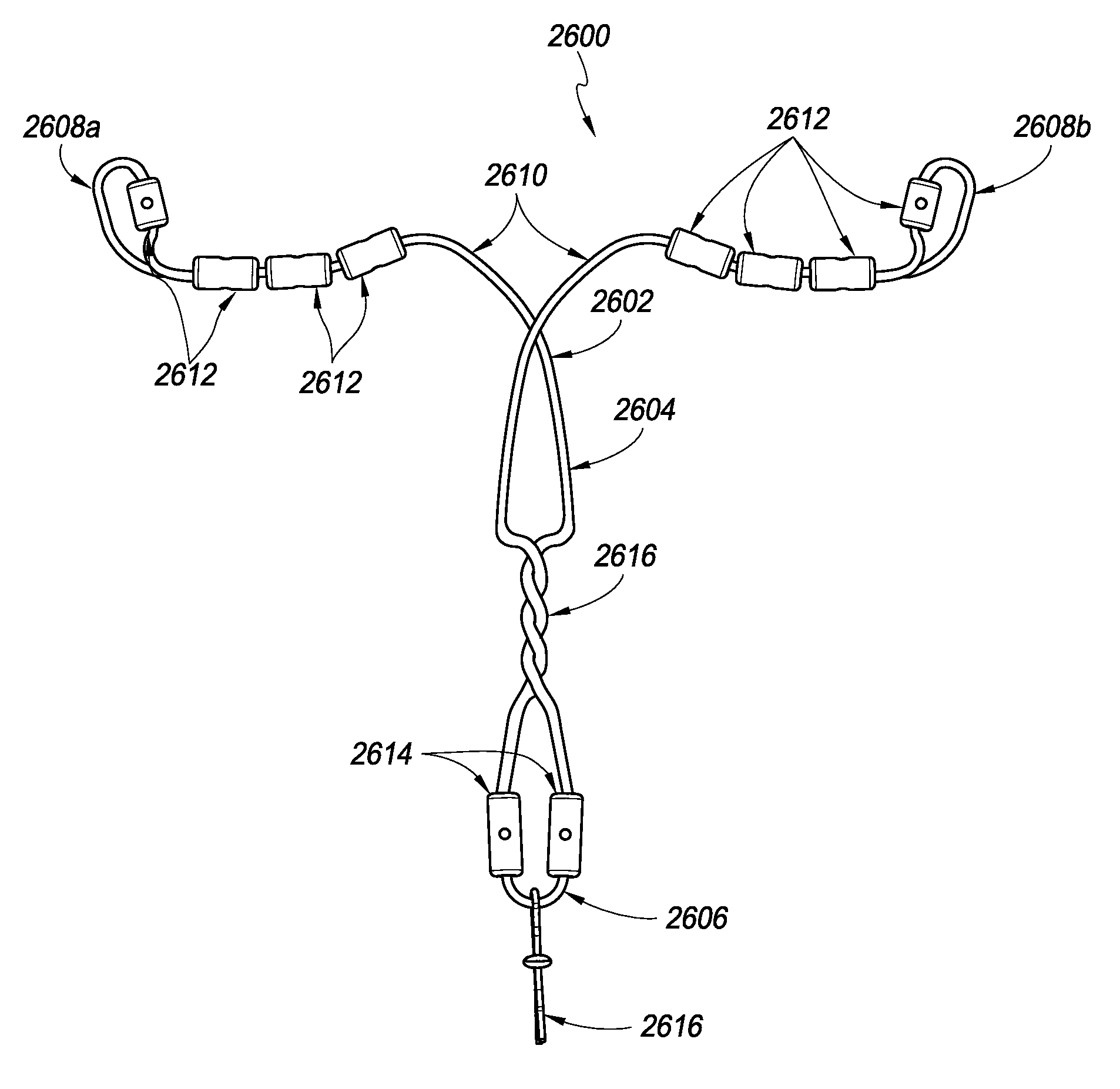
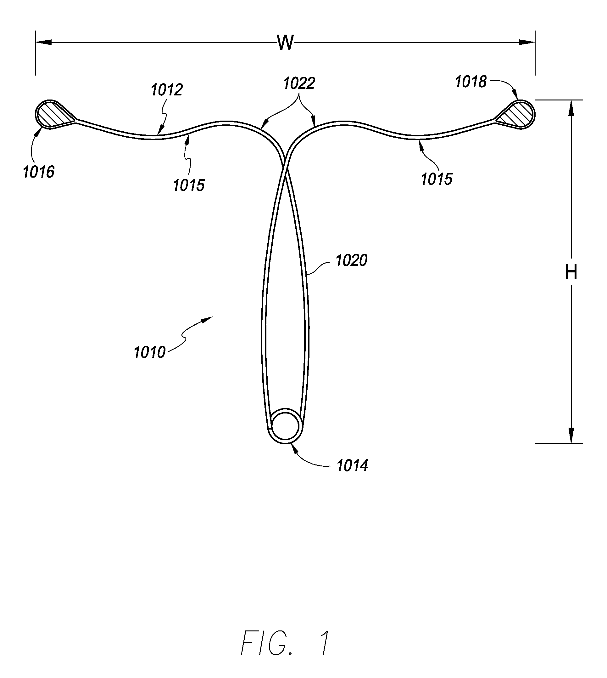
[0022]In another aspect, a shape memory, intrauterine, contraceptive device may include two tissue contact surfaces at or near opposing ends of the device, an expandable middle portion between the tissue contact surfaces, and a spring portion at or near a midpoint of the elongate member. The contraceptive device may be configured to move from a first, default configuration when unconstrained to a second, partially collapsed configuration when the two tissue contact surfaces are forced toward one another by an inner wall of a uterus. The expandable middle portion is expanded in the second shape such that it contacts the inner wall of the uterus to help prevent migration of the contraceptive device out of the uterus.

Problems solved by technology

Although both copper and progestin-releasing IUDs work well for contraception, both have common side effects.
The most common side effects with copper IUDs are abnormal bleeding and pain.
In addition to the above shortcomings, many currently available IUDs are at least slightly uncomfortable and / or challenging to deliver into the uterus.
Although this delivery method works well in many cases, the required size of the currently available IUDs typically requires a sheath having an outer diameter that can cause pain or discomfort upon insertion into a cervix.
In some cases, the pain can even be significant.

Method used


Image

  • Intrauterine contraceptive device
  • Intrauterine contraceptive device
  • Intrauterine contraceptive device

Examples


Embodiment Construction

[0046]Referring to FIG. 1, in one embodiment, a contraceptive intrauterine device (IUD) 1010 may include a shape memory, elongate member 1012 and two tissue contact members 1016, 1018 disposed at opposite ends of elongate member 1012. Elongate member 1012 may include a spring portion 1014, typically but not necessarily disposed approximately at a midpoint between the opposite ends of elongate member 1012, an expandable middle portion 1020, two arms 1015 extending from middle portion 1020, and bends 1022 between middle portion 1020 and arms 1015. All or a part of each tissue contact member 1016, 1018 may comprise a tissue contact surface, in other words, a surface that typically contacts an inner wall of a uterus when IUD 1010 is deployed in the uterus.

[0047]Elongate member 1012 is manufactured from a resilient, shape memory material, such as but not limited to Nitinol (nickel titanium alloy), spring stainless steel, other shape memory metal alloys, shape memory polymers, or the like...


PUM


Abstract

A method for promoting contraception by placing a contraceptive device within a uterus without blocking fallopian tubes may involve advancing a distal end of a delivery device through a cervix, advancing the contraceptive device comprising an elongate shape memory member out of the distal end of the delivery device and into the uterus, and limiting inferior migration of the contraceptive device within the uterus. Inferior migration may be limited by allowing the contraceptive device to assume a shape, when subjected to pressure that tends to cause a downward migration of the device within the uterus, in which an expandable middle portion of the device is expanded to contact the inner wall of the uterus and thus limit the downward migration of the device.

Description

CROSS-REFERENCE TO RELATED APPLICATIONS[0001]This application is a continuation-in-part of U.S. patent application Ser. No. 13 / 585,039, filed Aug. 14, 2012, the entirety of which is hereby incorporated by reference.BACKGROUND[0002]1. Field of the Invention[0003]The invention relates generally to medical devices. More specifically, the invention relates to an intrauterine device for contraception and method for use.[0004]2. Description of the Related Art[0005]Intrauterine devices (IUDs) are a commonly used form of contraception. There are two basic types of currently available IUDs—copper-releasing and progesterone-releasing. The copper IUD is a T-shaped device made of polyethylene wrapped with copper wire. The device acts as a foreign body within the uterus and releases copper to produce a chemical effect on the endometrium of the uterus and to alter the production of cervical mucus, thus producing a spermicidal environment.[0006]Progesterone-releasing IUDs are also T-shaped devices...

Claims


Application Information

Patent Timeline
Patent Type & Authority Patents(United States)
IPC IPC(8): A61F6/14
CPCA61F6/144A61F6/142A61F6/18
Inventor TAL, MICHAELKATZ, BOB H.DEBISSCHOP, MARK JAMESWILSON, PETESHIKHMAN, OLEG
Owner SEBELA VLC LTD
Why Eureka
Try Eureka