
Standby power shut-off outlet device and a control method for the same
a technology of standby power and outlet device, which is applied in the direction of emergency power supply arrangement, coupling device connection, pulse technique, etc., can solve the problems of wasting power and creating a risk of fire, affecting the and inconvenience for users, so as to efficiently interrupt the power consumed in the standby state, the effect of convenient operation of the outlet device and reducing the power consumed in the outl
- Summary
- Abstract
- Description
- Claims
- Application Information
AI Technical Summary
Benefits of technology
Problems solved by technology
Method used
Image

Examples
first embodiment
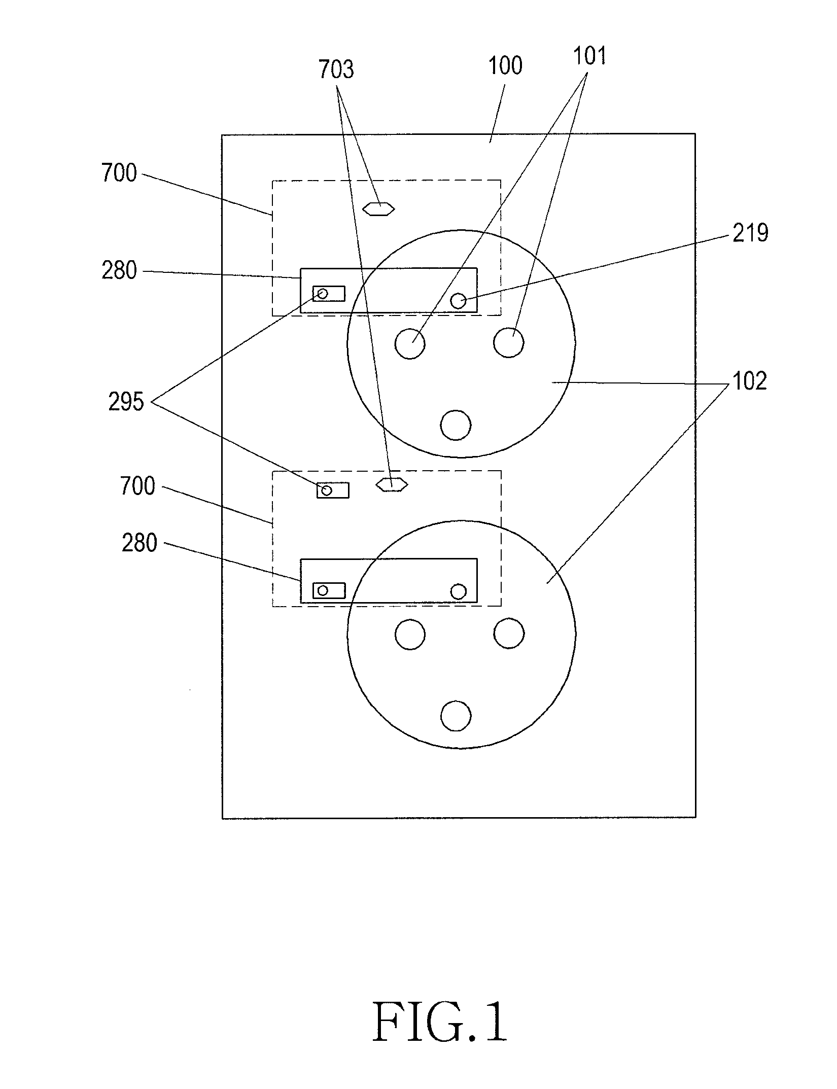
[0026]FIG. 1 is a diagram illustrating an outside of an outlet according to a first embodiment of the present invention.
[0027]Referring to FIG. 1, an outlet 100 includes one or more plug inserters 102 and one or more standby power interrupters 700. Here, the outlet 100 includes one standby power interrupter 700 corresponding to one plug inserter 102.
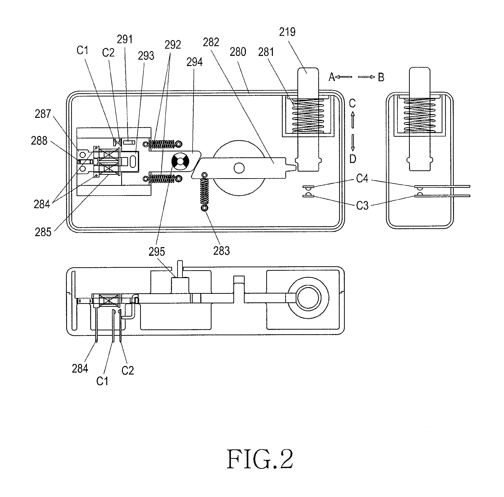
[0028]The standby power interrupter 700 includes a controller 701, an outlet power source unit 702, a jumper 703, a memory 704, an outlet switch unit 280, a current transformer 705, and a switch driver 706, and the plug inserter 102 includes a plug inserting hole 101.
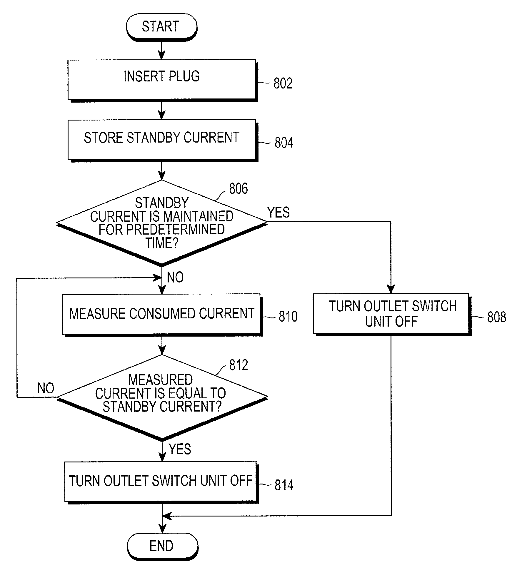
[0029]The standby power interrupter 700 performs an operation of automatically interrupting standby power according to a state of an electronic product connected to the outlet 100. That is, the controller 701 of the standby power interrupter 700 measures a current flowing in an inside of the electronic product connected to the outlet 100 and determines whether a power source...
second embodiment
[0070]FIG. 9 is a diagram illustrating an outside of an outlet according to a second embodiment of the present invention.
[0071]Referring to FIG. 9, an outlet 900 includes one or more plug inserters 901 and one or more standby power interrupters 1003. Here, the outlet 900 includes one standby power interrupter 1003 corresponding to one plug inserter 901. Further, the outlet 900 may further include a remote switch unit 903 installed in a place allowing an easy access by a user.
[0072]FIG. 10 is a diagram illustrating an inside of an outlet according to a second embodiment of the present invention.
[0073]Referring to FIG. 10, the outlet 900 includes a controller 1001, a backup power source unit 1002, one or more standby power interrupters 1003, an outlet power source unit 1004, and a mode selector 1005, and may further include the remote switch unit 903 in an outside of the outlet 900.
[0074]The controller 1001 may include a memory 1009 in an inside or an outside of the controller 1001, a...
PUM
 Abstract
Description
Claims
Application Information