
Comminuting device including a rotary current asynchronous motor and a non-positive traction drive and method for its operation

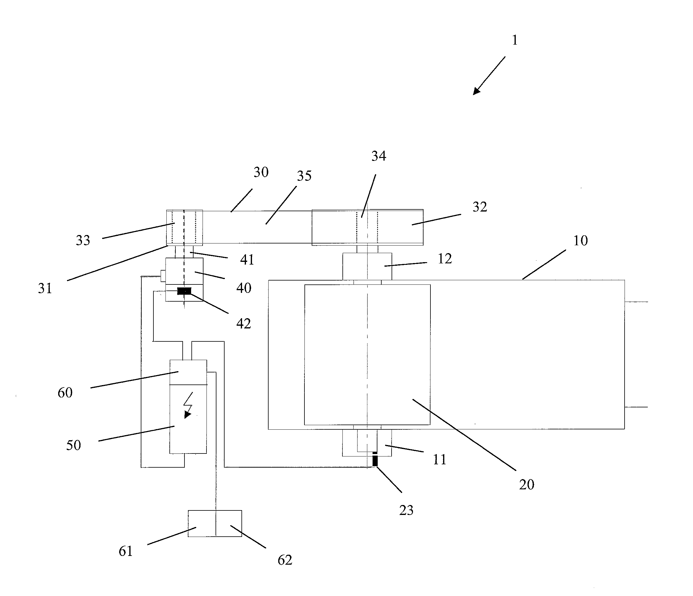
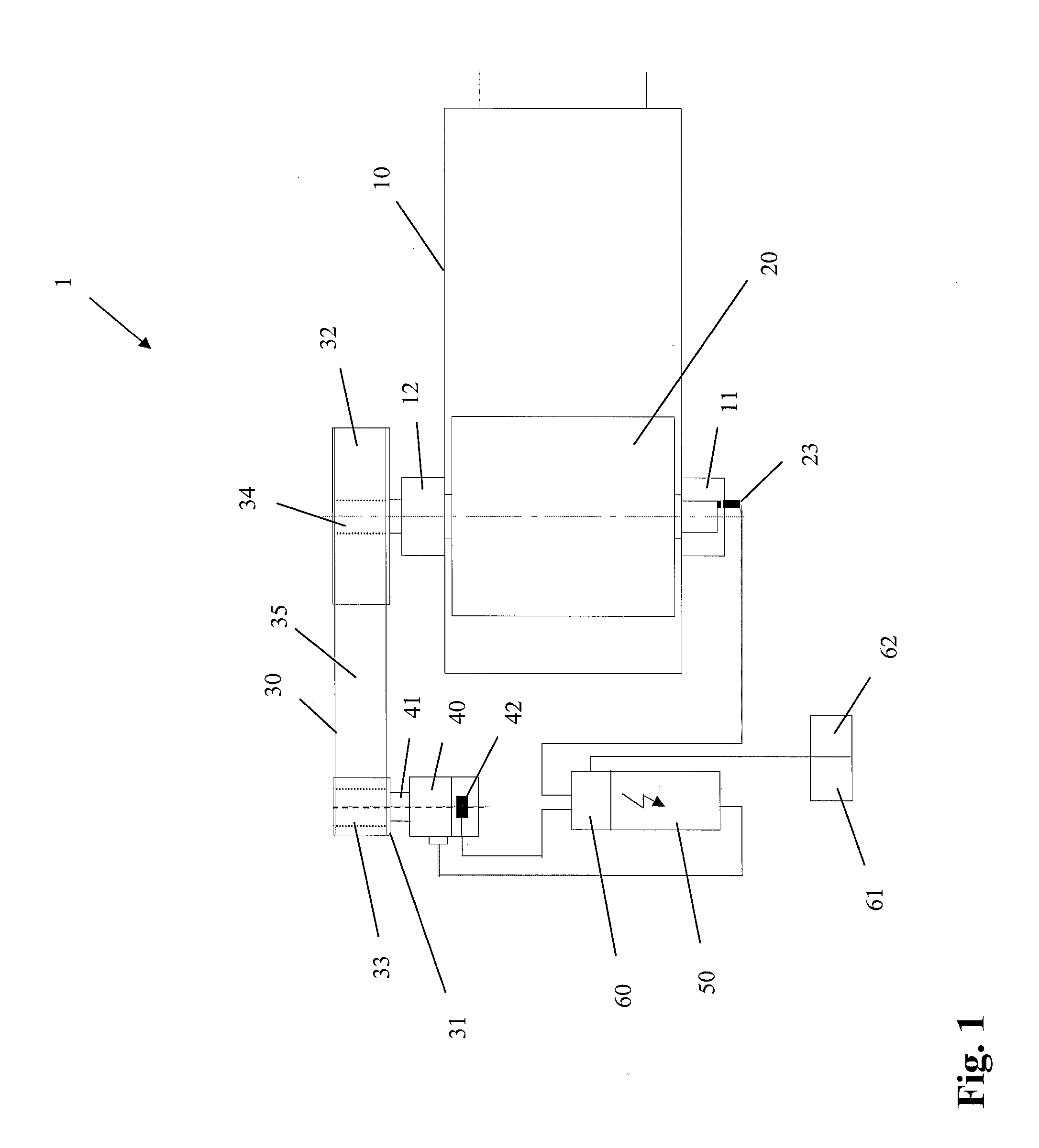
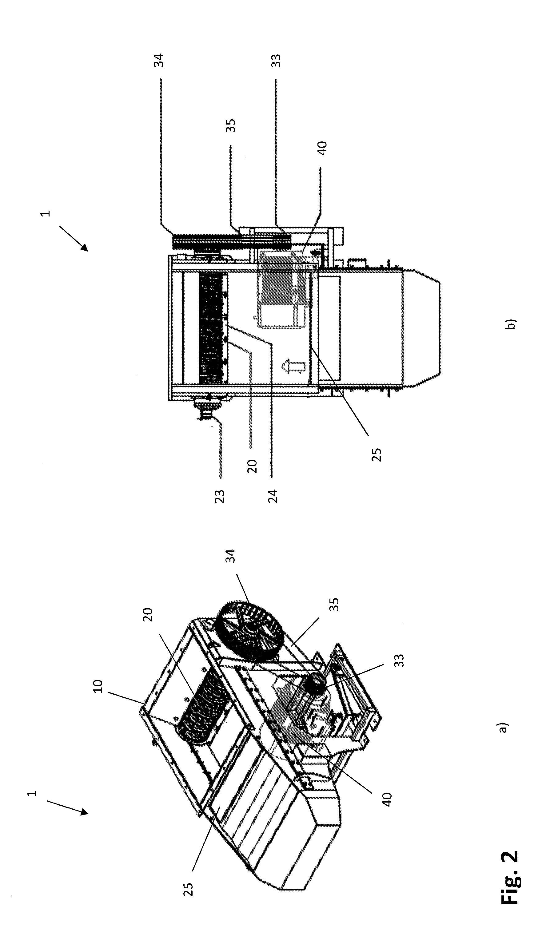
a comminuting device and asynchronous motor technology, applied in the direction of ac motor control, tube/lamp material recovery, tube/lamp repair/regeneration, etc., can solve the problems of high load of individual machine elements, vibration, and impact-loaded operation of the comminuting device, and achieve the effect of reducing the risk of damage to the gear mechanism, reducing the risk of damage, and improving the service li

Active Publication Date: 2016-01-12
VECOPLAN
View PDF8 Cites 0 Cited by
  • Summary
  • Abstract
  • Description
  • Claims
  • Application Information

AI Technical Summary

Benefits of technology

The invention is a method for operating a comminuting device that reduces wear and tear in the gear mechanism while also maintaining a continuous operation. By controlling the slip operation of the traction drive, the method prevents excessive slip or low rotational speed of the comminuting rotor. This is achieved by designing the traction drive in a manner that allows for a reliable continuous comminuting process and detects any malfunctions caused by uncomminuted extraneous material. The method effectively requires interruption only if the slip exceeds the first threshold, which is equivalent to the detection of obstructing extraneous material. Overall, the method improves the efficiency and reliability of the comminuting process.

Problems solved by technology

Considering that with many kinds of materials to be comminuted the comminution process is not performed in a smooth manner, but may be shock-loaded, the requirements are high concerning the stability of the device and particularly the mounting of the rotating parts.
Depending on the specific application, mechanical gear mechanisms may produce strong running noises or may lead to a harsh, impact-loaded operation of the comminuting device, accompanied by all relevant drawbacks such as noise, vibrancy, and high loads of individual machine elements.
Particularly in the case of jamming caused by the occurrence of uncomminutable extraneous materials, the gear mechanism may be severely damaged and shafts may even break.
Conventional belt drives for comminuting devices are however subject to considerable wear, which results in comparatively short maintenance intervals that must be observed.
Further, the operation of such comminuting devices can be complicated because depending on the material to be comminuted it may require frequent stoppage or reversing of the rotor if comminuting material has accumulated.
The interruption of the comminuting process can often not be prevented, even if the feeding rate of the material to be comminuted is reduced.

Method used


Image

  • Comminuting device including a rotary current asynchronous motor and a non-positive traction drive and method for its operation
  • Comminuting device including a rotary current asynchronous motor and a non-positive traction drive and method for its operation
  • Comminuting device including a rotary current asynchronous motor and a non-positive traction drive and method for its operation

Examples


Embodiment Construction

[0007]Surprisingly, that object is achieved already by a method for operating a comminuting device comprising the features of various embodiments of the present invention. The method of the invention is characterized in that if the amount of a predetermined second slip threshold value of the traction drive is below the first slip threshold value, said frequency converter is controlled in a slip operating phase for controlling the traction drive slip to a predetermined third slip threshold value and for reducing the output torque from the rotary current electric motor, for continuing the operation of the comminuting device.

[0008]Due to the fact that in the method of the invention a slip operation is carried out if a second threshold for the traction drive slip is exceeded, during which slip operation a third predetermined slip threshold value for the traction drive slip is selected or controlled either by a simple open loop control or via a closed loop control, it can be achieved tha...


PUM


Abstract

A comminuting rotor is driven by a rotary current electric motor via a non-positive traction drive, wherein said rotary current electric motor is energized by a controlled frequency converter for operating the comminuting rotor at a predetermined rotational speed during the normal operating phase. A degree of slip of the traction drive is determined and monitored and the rotary current electric motor is controlled for being powered off if a first slip threshold value is exceeded. If a predetermined second threshold of the traction drive slip is exceeded, which is below said first slip threshold, for continuing the operation of the comminuting device, the frequency converter is controlled in a slip operating phase for a closed or open loop control of the traction drive slip to a predetermined third slip threshold value and for reducing the torque output from the rotary current electric motor.

Description

CROSS-REFERENCE TO RELATED APPLICATIONS[0001]This application claims priority from German Patent Application No, 10 2013 114 782.8, filed Dec. 23, 2013, which is incorporated by reference herein in its entirety.BACKGROUND OF THE INVENTION[0002]The invention relates to a method for operating a comminuting device, in which method a comminuting rotor is driven by a driving unit at least comprising a rotary current electric motor, via a non-positive traction drive, in particular a belt drive, wherein said rotary current electric motor is energized by a controlled frequency converter, for operating the comminuting rotor at a predetermined rotational speed during the normal operating phase, and wherein a degree of slip of the traction drive is determined and monitored and the rotary current electric motor is controlled for being powered off if a first slip threshold value is exceeded. The invention also relates to a comminuting device for carrying out such a method.[0003]Such comminuting ...

Claims


Application Information

Patent Timeline
IPC IPC(8): B02C25/00H01J9/52B02C18/00B02C18/24H02P27/06
CPCB02C25/00B02C18/0084B02C18/24H01J9/52H02P27/06
Inventor LIPOWSKI, WOLFGANG
Owner VECOPLAN
Learn More