Oscillatory drive

a technology of oscillatory drive and oscillator, which is applied in the direction of grinding machine components, grinding/polishing apparatus, grinding machines, etc., can solve the problems of low efficiency, user may feel vibrations to a considerable extent, and the power of the oscillatory drive is limited, so as to achieve the effect of minimizing wear during operation

Inactive Publication Date: 2005-08-09
C & E FEIN
View PDF10 Cites 44 Cited by
  • Summary
  • Abstract
  • Description
  • Claims
  • Application Information

AI Technical Summary

Benefits of technology

[0010]It is an object of the invention to provide an oscillatory drive, which minimizes wear during operation.

Problems solved by technology

However, these devices have a considerable noise emission and a low efficiency.
Also a user may feel vibrations to a considerable extent, depending on the load to which the tool is subjected.
This arrangement suffers from the drawback that there is only a point like contact between the crowned outer ring of the needle bearing and the flat surfaces of the pivot lever affiliated therewith.
Thereby, the power of the oscillatory drive is limited.
Also a relatively high wear must be taken into account.

Method used


Image

  • Oscillatory drive
  • Oscillatory drive
  • Oscillatory drive

Examples


Embodiment Construction

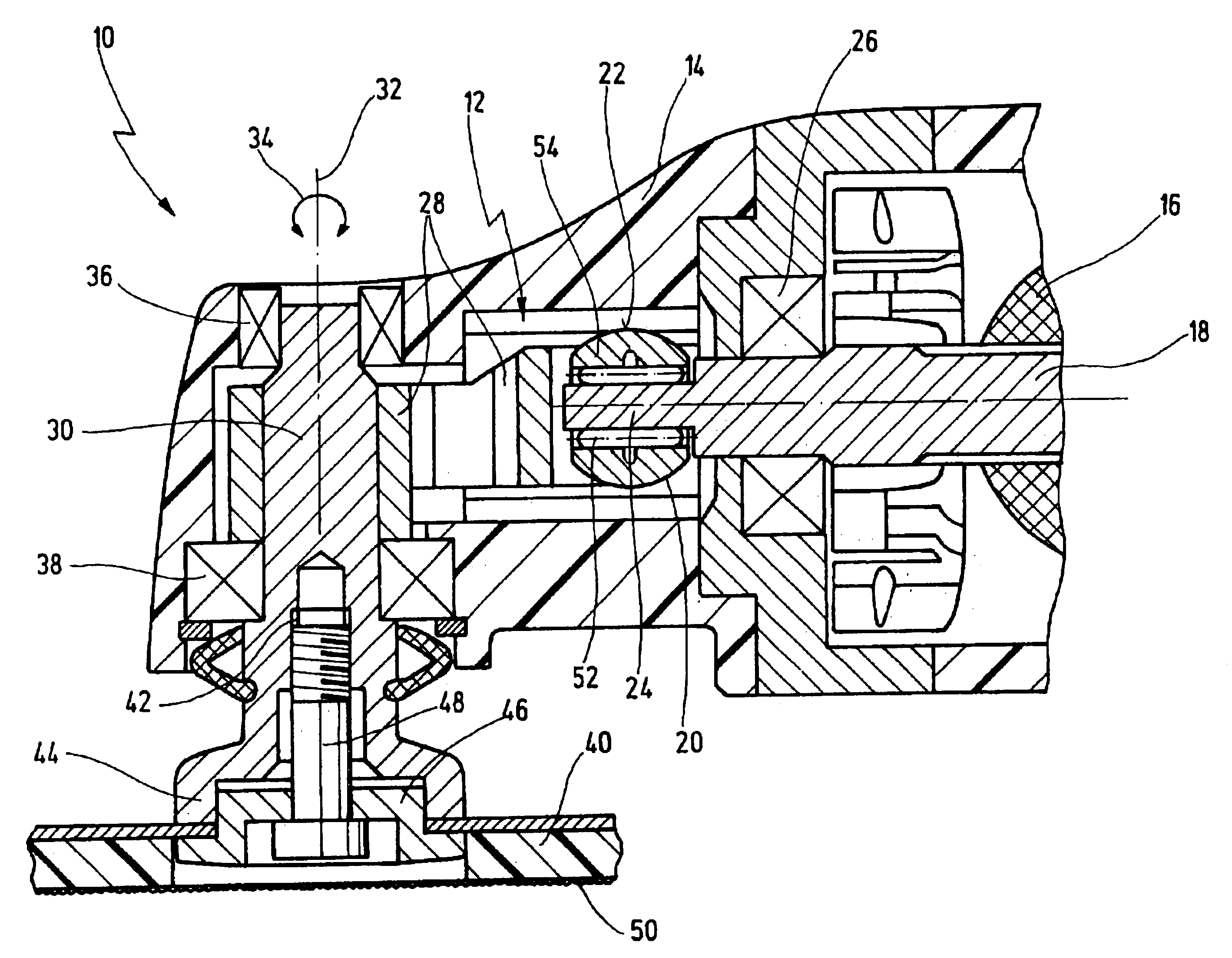
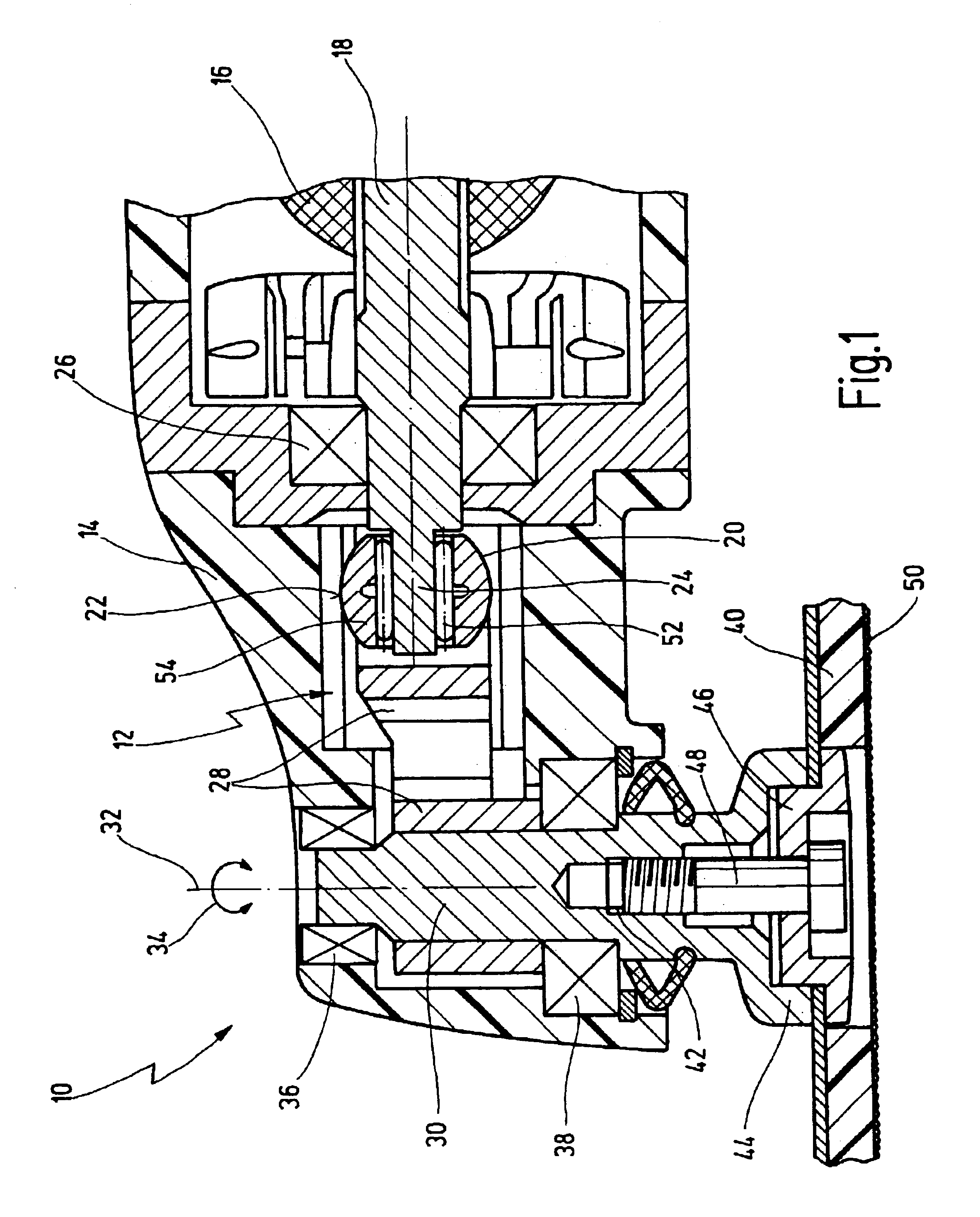
[0045]In FIGS. 1 and 2 a power tool according to the invention is shown and depicted in total with reference numeral 10. It is designed as a handheld power tool, wherein the tool 40 is driven at high frequency of roughly 5,000 to 30,000 oscillations per minute and at a small pivot angle of roughly 0.5 to 7° about the longitudinal axis 32 of a tool drive shaft 30, as shown by double arrow 34. Such a power tool 10 can be utilized for effecting various operations, in particular for grinding or polishing work, for cutting work, for sawing work, and so on.

[0046]The power tool 10 comprises an oscillatory drive which is designated in total with reference numeral 12, the oscillatory drive converting a rotating motion of a drive shaft 18 driven by an electric motor 16 into an oscillating motion of the tool drive shaft 30.

[0047]In the case shown, the tool drive shaft 30 is arranged perpendicularly with respect to the drive shaft 18.

[0048]The oscillatory drive 12 comprises an eccentric element...


PUM


Abstract

An oscillatory drive comprising a rotating drive shaft is disclosed. The oscillatory drive is driven by an eccentric element that is coupled via a pivot element to a tool drive shaft arranged at an angle to the drive shaft for oscillatingly driving the tool drive shaft pivoting back and forth about its longitudinal axis. The eccentric element comprises a spherical outer ring which is guided within an at least partially cylindrical inner surface of the pivot element. By spring biasing the free end of the pivot element at both outer sides against the housing, efficiency is improved and vibrations are reduced.

Description

[0001]This application claims priority of pending German Patent Application Nos. 102 20 326.1 and 102 20 325.3 filed on Apr. 30, 2002.BACKGROUND OF THE INVENTION[0002]The invention relates to an oscillatory drive comprising a housing within which a drive shaft being rotatingly driven is arranged, an eccentric element driven by the drive shaft, and a tool drive shaft, wherein the eccentric element is coupled by means of a pivot element to a tool drive shaft for oscillatingly driving same about its longitudinal axis.[0003]The invention further relates to a power tool comprising such an oscillatory drive.[0004]Oscillatory drives have been used for many years, in particular, for performing special operations with power tools. For example, oscillatory drives are used in a variety of power tools for performing various grinding and polishing operations, cutting operations, e.g. for cutting out glass panes of windshields, for sawing, e.g. for sawing car body sheets and the like.[0005]To thi...

Claims


Application Information

Patent Timeline
Patent Type & Authority Patents(United States)
IPC IPC(8): B24B23/00B24B47/00B24B23/04B24B47/10B24B41/00B24B41/04
CPCB24B23/04B24B41/04B24B47/10
Inventor POLLAK, ROLANDFELGER, ADAM
Owner C & E FEIN
Why Eureka
Try Eureka