Micromechanical device and corresponding production method

a micro-mechanical device and production method technology, applied in the direction of optical elements, generators/motors, television systems, etc., can solve the problems of affecting the sealing effect of the bonding layer, so as to avoid intermetallic corrosion and avoid intermetallic corrosion

Active Publication Date: 2021-09-28
ROBERT BOSCH GMBH
View PDF15 Cites 0 Cited by
  • Summary
  • Abstract
  • Description
  • Claims
  • Application Information

AI Technical Summary

Benefits of technology

[0007]Example embodiments of the present invention may provide the capability for producing a micromechanical apparatus with reduced sensitivity, in which the metallic corrosion path (current path) between the environment and the encapsulated interior is interrupted by way of a trench structure, so that the environment and the encapsulated interior are galvanically disconnected with no need for the metal layer to be separately patterned. The metal layer thus remains intact in the interior, and is interrupted on the non-flat side walls of the trench. Robustness with respect to moisture and various environmental influences on the micromechanical apparatus can thereby be particularly advantageously enhanced.
[0009]According to a preferred refinement of the micromechanical apparatus according to the present invention, the front side of the base substrate and the trench are coated with two different metal layers. This results in a plurality of additional applications, and at the same time avoids intermetallic corrosion, which can occur in applications in which metals having very different electrochemical potentials, such as silver / aluminum, are used.
[0010]According to a preferred refinement of the micromechanical apparatus according to the present invention, the base substrate and the trench are coated with a metal layer made of silver, on which a metal layer made of aluminum is applied. Many of the tasks of micromechanical apparatuses having a microchip can thereby be performed particularly advantageously, while intermetallic corrosion can be avoided.
[0011]According to a preferred refinement of the micromechanical apparatus according to the present invention, the trench has a width from 10 micrometers to 100 micrometers and a depth from 20 micrometers to 200 micrometers. The current path between the two sides of the trench can be interrupted effectively by selecting these dimensions.

Problems solved by technology

If this metal stack corrodes in response to moisture, the seal-glass bond becomes detached from the adhesion layer and sufficient sealing can possibly be impaired.

Method used


Image

  • Micromechanical device and corresponding production method
  • Micromechanical device and corresponding production method

Examples


first embodiment

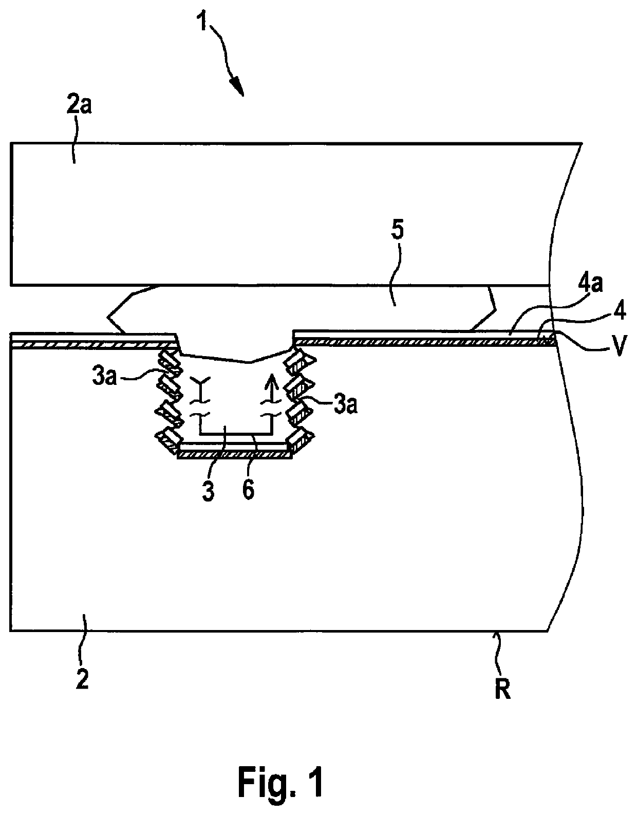
[0019]FIG. 1 is a schematic depiction, in cross section, to explain a micromechanical apparatus in accordance with the present invention.

[0020]In FIG. 1, the reference character 1 identifies the micromechanical apparatus, which has a base substrate 2 having a front side V and a rear side R. The reference character 2a identifies a cap substrate, 3 a surrounding trench, 3a non-flat side walls of trench 3, 4 a first metal layer and 4a a second metal layer, 5 a seal-glass closure, and 6 an interrupted current path along the non-flat side walls 3a as a result of a nonconforming embodiment of metal layers 4, 4a.

[0021]One conventional method for galvanically disconnecting a metal layer and / or several metal layers is selective removal of the metal in certain regions, i.e., patterning of the metal, for instance by lithography and subsequent etching.

[0022]The example embodiment of the present invention includes avoidance of a lithography and etching step of this kind, by the fact that even b...

second embodiment

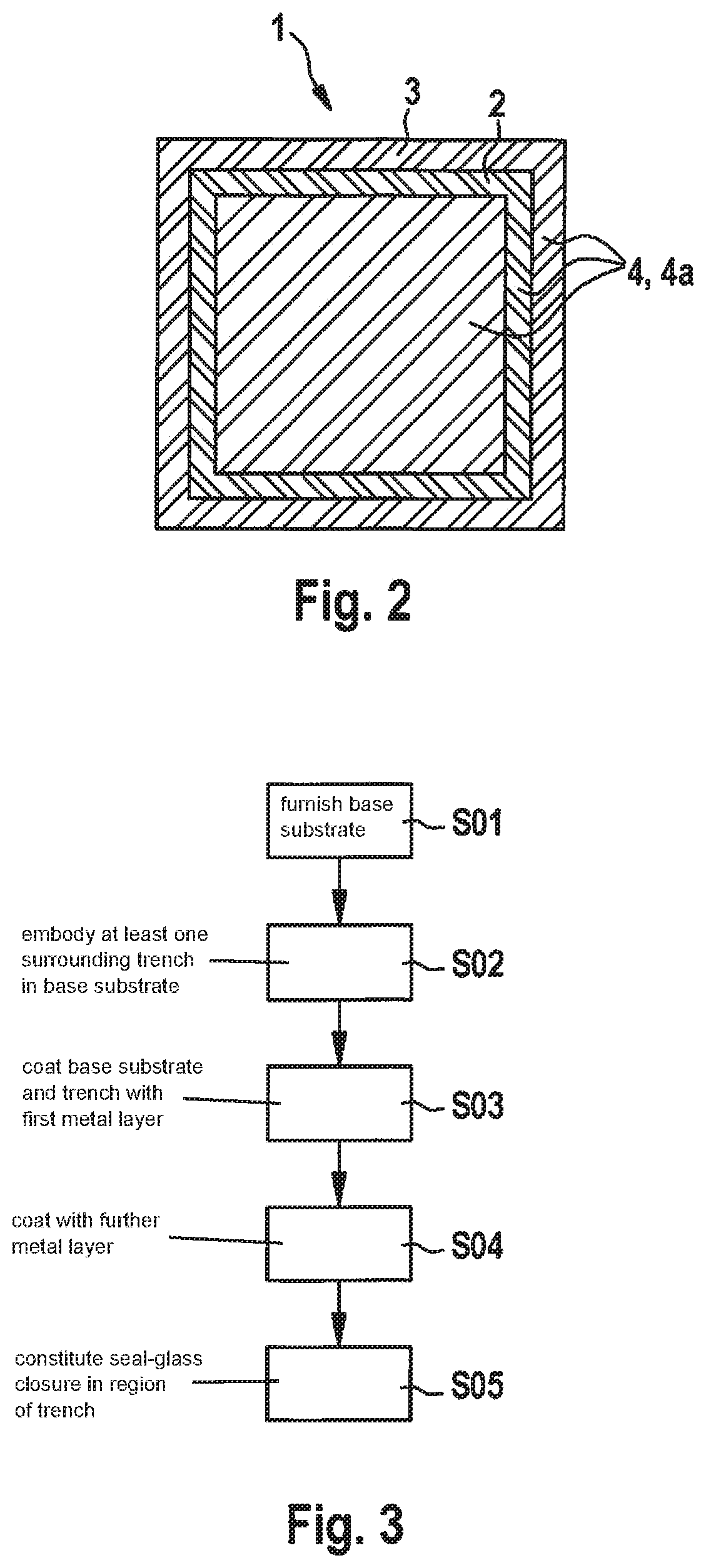
[0029]FIG. 3 is a schematic flow chart to explain a method for producing a micromechanical apparatus, having a microchip with decreased sensitivity to metal corrosion, in accordance with a

[0030]In a step S01, a base substrate 2 is furnished. In a step S02, at least one surrounding trench 3 having non-flat side walls 3a is embodied in this base substrate 2, and in a step S03, base substrate 2 and trench 3 are coated with a first metal layer 4 made, for example, of silver. In a step S04, further coating can occur with at least one further metal layer 4a that has a metal (e.g. aluminum) that is dissimilar to the metal of first metal 4; and in a step S05, seal-glass closure 5 is constituted in conventional fashion in the region of trench 3.

[0031]Although the present invention has been described with reference to preferred exemplifying embodiments, it is not limited thereto. In particular, the materials and topologies that are recited are merely examples and are not limited to the exampl...


PUM

PropertyMeasurementUnit
depthaaaaaaaaaa
widthaaaaaaaaaa
depthaaaaaaaaaa

Abstract

A micromechanical apparatus and a corresponding production method are described. The micromechanical apparatus encompasses a base substrate having a front side and a rear side; and a cap substrate, at least one surrounding trench having non-flat side walls being embodied in the front side of the base substrate; the front side of the base substrate and the trench being coated with at least one metal layer; the non-flat side walls of the trench being covered nonconformingly with the metal so that they do not form an electrical current path in a direction extending perpendicularly to the front side; and a closure, in particular a seal-glass closure, being embodied in the region of the trench between the base substrate and the cap substrate.

Description

FIELD[0001]The present invention relates to a micromechanical apparatus and to a corresponding production method.BACKGROUND INFORMATION[0002]Although any micromechanical components are also usable, the present invention and the problem on which it is based will be explained with reference to components having microchips.[0003]Microchips are subject to stringent requirements regarding sealing. For instance, they must pass so-called moisture tests with no occurrence of corrosion, for example due to a redox reaction, for instance intermetallic corrosion of an aluminum / silver metal stack exposed at the sawn face of the chip. The metal stack is continuous, i.e., deposited over the entire surface of the chip, and is thus also the substrate of a seal-glass bond that is described, for example, in German Patent Application No. DE 10 2005 040 789 A1. If this metal stack corrodes in response to moisture, the seal-glass bond becomes detached from the adhesion layer and sufficient sealing can po...

Claims


Application Information

Patent Timeline
Patent Type & Authority Patents(United States)
IPC IPC(8): B81B7/02B81C1/00
CPCB81B7/02B81C1/00246B81B2203/033B81C2201/013B81C2203/0109B81C2203/019B81C2203/0118B81B7/0058B81B2203/0338B81C2201/0112B81B1/00
Inventor BAADER, JOHANNESSCHORR, NICOLASSTRAUB, RAINERPINTER, STEFANSTEIGERT, TINA
Owner ROBERT BOSCH GMBH
Why Eureka
Try Eureka