Seat-mounted airbag apparatus and vehicle seat

a seat-mounted airbag and seat technology, applied in the direction of vehicle components, pedestrian/occupant safety arrangements, vehicular safety arrangments, etc., can solve the problem of inability to restrain the occupant from the front, and achieve the effect of preventing or effectively inhibiting the inadvertent interference of the shoulder airbag and deploying smoothly

Active Publication Date: 2015-09-15
TOYOTA JIDOSHA KK
View PDF18 Cites 21 Cited by
  • Summary
  • Abstract
  • Description
  • Claims
  • Application Information

AI Technical Summary

Benefits of technology

[0009]In this aspect, the inflator is activated when the vehicle is involved in a frontal collision, for example. Consequently, gas is supplied into the shoulder airbag that is formed in a long bag shape and is housed in one side portion of the seatback of the vehicle seat, causing the shoulder airbag to inflate and deploy. This shoulder airbag is fixed at one longitudinal end portion to the seatback frame, and extends from an upper end portion of the side portion toward the vehicle front side when inflated and deployed. Further, the expanding member expands between the inflated and deployed shoulder airbag and the seatback frame. This expanding member opposes one shoulder of the seated occupant from the side, and keeps the other longitudinal end portion of the shoulder airbag opposing the one shoulder from the front. As a result, the one shoulder is able to be restrained from both the side and the front.
[0011]In this aspect, the inflator is activated when the vehicle is involved in a frontal collision, for example. Consequently, gas is supplied into the shoulder airbag that is formed in a long bag shape and is housed in one side portion of the seatback of the vehicle seat, causing the shoulder airbag to inflate and deploy. This shoulder airbag is fixed at one longitudinal end portion to the seatback frame, and extends front an upper end portion of the side portion toward the vehicle front side when inflated and deployed. Further, the expanding member expands between the inflated and deployed shoulder airbag and the seatback frame. This expanding member opposes one shoulder of the seated occupant from the side, and keeps the other longitudinal end portion of the shoulder airbag extended toward the vehicle lower side. In addition, the other longitudinal end portion of the shoulder airbag is made to oppose the one shoulder from the front by the retracting device pulling down the inflated and deployed shoulder airbag toward the seat width direction inside by driving force. As a result, the one shoulder is able to be restrained from both the side and the front.
[0012]Moreover, the inflated and deployed shoulder airbag is made to oppose one shoulder by being pulled down toward the seat width direction inside, so the shoulder airbag is able to be inflated and deployed farther to the seat width direction outside than the one shoulder. Accordingly, it is possible to prevent or effectively inhibit the shoulder airbag from inadvertently interfering with the one shoulder, so the shoulder airbag can inflate and deploy smoothly.

Problems solved by technology

With this kind of airbag apparatus, the airbag bag body is configured to deploy next to the occupant, and is thus unable to restrain the occupant from the front.

Method used


Image

  • Seat-mounted airbag apparatus and vehicle seat
  • Seat-mounted airbag apparatus and vehicle seat
  • Seat-mounted airbag apparatus and vehicle seat

Examples


first example embodiment

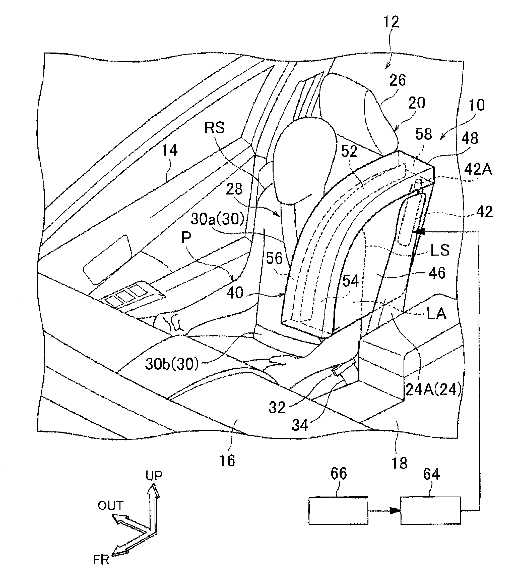
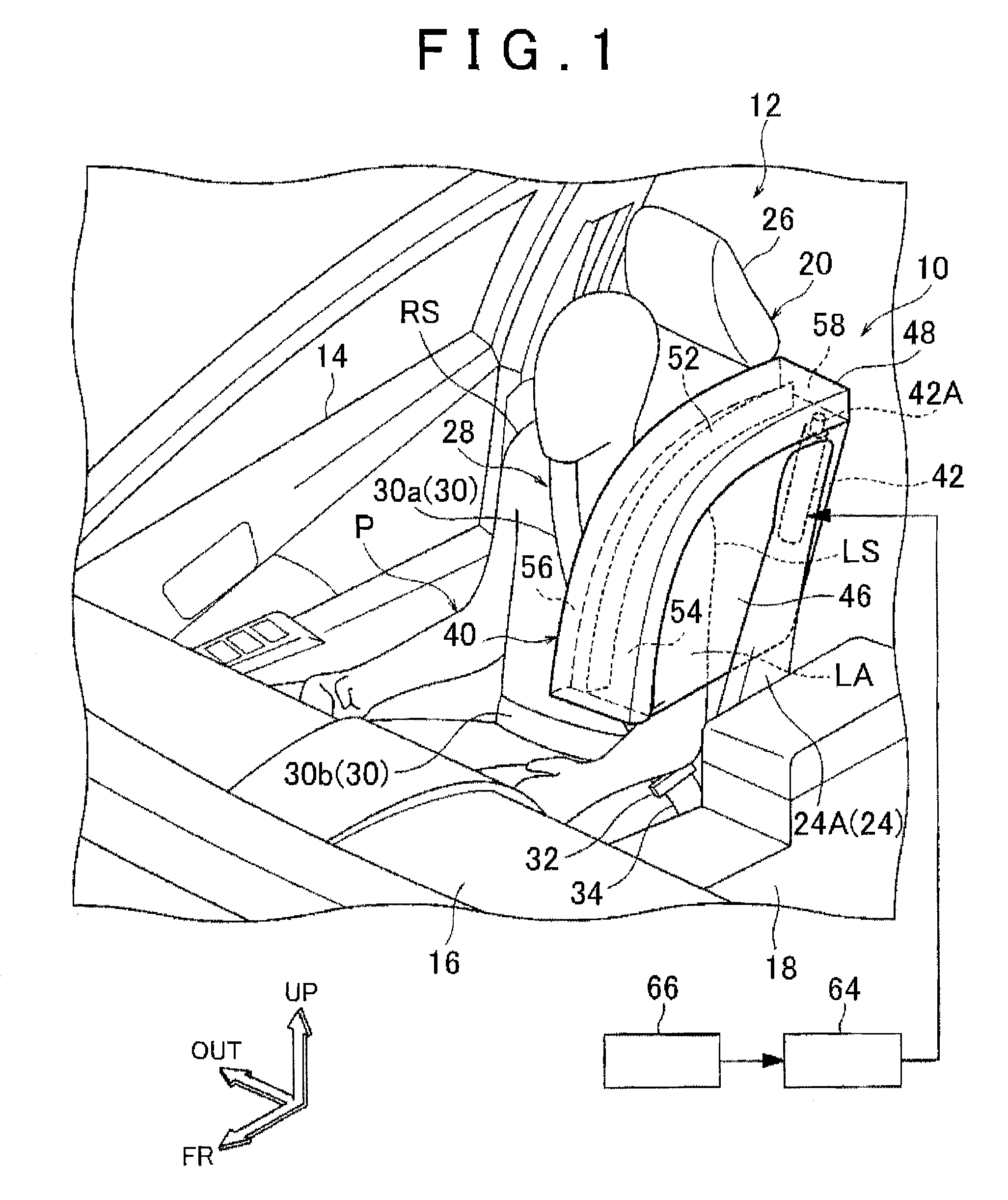
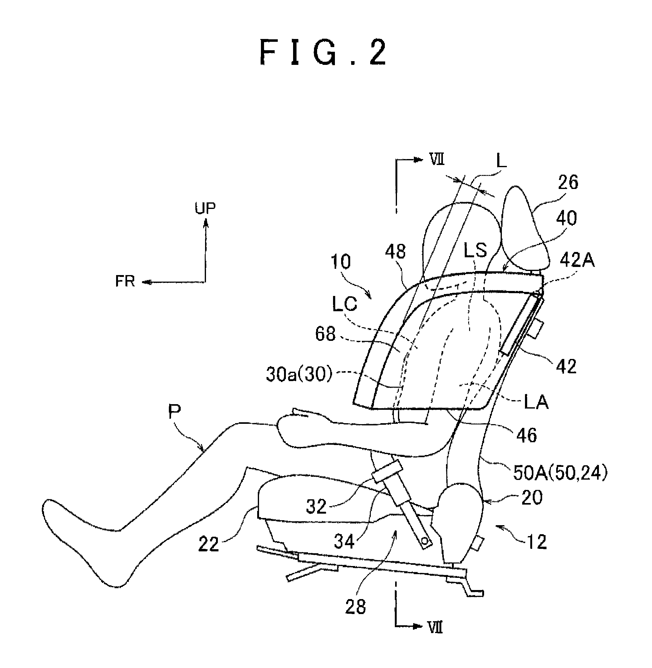
[0036]A seat-mounted airbag apparatus 10 and a vehicle seat 12 according to a first example embodiment of the invention will now be described with reference to FIGS. 1 to 9. In the drawings, arrow FR indicates a forward direction (advancing direction) with respect to a vehicle, arrow UP indicates an upward direction with respect to the vehicle, and arrow OUT indicates an outside in a vehicle width direction. Hereinafter, unless otherwise specific, when directions of front and rear, up and down, and left and right are used, they will refer to front and rear in a vehicle longitudinal direction, left and right in a vehicle left-right direction (i.e., the vehicle width direction), and up and down in a vehicle up-down direction, respectively.

[0037](Structure)

[0038]The vehicle seat 12 shown in FIGS. 1 to 4 is a front seat of a vehicle. More specifically, in this case, the vehicle seat 12 is a passenger seat of a left-hand drive vehicle, and is arranged on a right side of a vehicle cabin f...

second example embodiment

[0075]FIGS. 10A and 10B are perspective views from the same direction as FIG. 4, of a second example embodiment of the invention. The structure of a seat-mounted airbag apparatus 70 in this example embodiment differs from the seat-mounted airbag apparatus 10 according to the first example embodiment described above. This seat-mounted airbag apparatus 70 is configured such that the shoulder airbag 40 inflates and deploys farther to the seat width direction outside than it does in the first example embodiment, and the inflated and deployed shoulder airbag 40 is pulled down toward the vehicle width direction outside (i.e., the seat width direction inside) by a retracting device 71.

[0076]The retracting device 71 is configured similar to a so-called pre-tensioner, and a micro gas generator is housed inside of a main body portion 72 that is fixed to a lower end portion of the seatback frame 50. This retracting device 71 is configured to retract one end portion of a wire 74 (a long flexibl...

third example embodiment

[0081]FIG. 11 is a perspective view similar to FIG. 6, of the structure of the main parts of a seat-mounted airbag apparatus 80 according to a third example embodiment of the invention. In this example embodiment, a partitioning piece 81 extends out from a rear end portion of the tether 52. This partitioning piece 81 extends out so as to extend toward the vehicle width direction inside when the shoulder airbag 40 is in the inflated and deployed state. The left chamber 54 is partitioned off from a gas inflow chamber 82 that houses the gas ejection portion 42A of the inflator 42 by this partitioning piece 81. The gas inflow chamber 82 is communicated with the right chamber 56. Also, in this example embodiment, a front end communication hole 84 is formed between the front end portion of the tether 52 and the front end portion of the shoulder airbag 40. The left and right chambers 54 and 56 are communicated together via this front end communication hole 84. The other structure in this e...


PUM


Abstract

A seat-mounted airbag apparatus includes an inflator that is provided in a vehicle seat and generates gas by being activated; a shoulder airbag that is formed in a long bag shape and is housed in one side portion of a seatback of the vehicle seat, with one longitudinal end portion being fixed to a seatback frame, the shoulder airbag inflating and deploying by the gas being supplied there into, and extending from an upper end portion of the side portion toward a vehicle front side; and an expanding member that expands between the inflated and deployed shoulder airbag and the seatback frame, and that opposes one shoulder of a seated occupant from a side, and keeps the other longitudinal end portion of the shoulder airbag in a position opposing the one shoulder from the front.

Description

INCORPORATION BY REFERENCE[0001]The disclosure of Japanese Patent Application No. 2013-206571 filed on Oct. 1, 2013 including the specification, drawings and abstract is incorporated herein by reference in its entirety.BACKGROUND OF THE INVENTION[0002]1. Field of the Invention[0003]The invention relates to a seat-mounted airbag apparatus mounted in a vehicle seat, and a vehicle seat.[0004]2. Description of Related Art[0005]Japanese Patent Application Publication No. 2012-051557 (JP 2012-051557 A) describes an airbag apparatus mounted in a vehicle seat. With this airbag apparatus, an airbag bag body has an inflating portion and at least one non-inflating portion. A tether that is joined to a seatback frame passes through an opening formed in the non-inflating portion and is connected to a front end of the airbag bag body. This tether effectively restrains the occupant by contacting both the airbag bag body and the occupant when the airbag bag body deploys, and controls the deployment...

Claims


Application Information

Patent Timeline
Patent Type & Authority Patents(United States)
IPC IPC(8): B60R21/16B60R21/231B60R21/233B60R21/207B60R21/00
CPCB60R21/231B60R21/207B60R21/233B60R2021/0004B60R2021/0006B60R2021/0058B60R2021/23316B60R21/2334B60R2021/23107B60R2021/23388
Inventor YASUOKA, SHIRO
Owner TOYOTA JIDOSHA KK
Why Eureka
Try Eureka