Adjustable spanner

a technology of adjustable spanners and adjustable bars, which is applied in the direction of wrenches, screwdrivers, manufacturing tools, etc., can solve the problems of restricting the movement of the fastening device, and achieve the effect of quick turning of objects and satisfactory structural strength

Active Publication Date: 2015-11-24
APEX BRANDS
View PDF30 Cites 3 Cited by
  • Summary
  • Abstract
  • Description
  • Claims
  • Application Information

AI Technical Summary

Benefits of technology

[0008]Furthermore, the adjustable spanner is capable of being turned relatively to the object, in a second direction which is opposite to the first direction. In this operation, the moving member moves relative to the grip while the first fastening device moves in the slot and urges the elastic member, with the first jaw carried by the moving member to move away from the second jaw until the moving member and first fastening device stop, with a second clamping distance larger than the first clamping distance defined between the first and second jaws when the moving member stops, and with the moving member being able to return to the relative position where the first and second jaws define the first clamping distance by the elastic member.
[0009]It is an object of an embodiment of the present invention to provide an adjustable spanner for quickly turning an object, and it has a satisfactory structural strength.
[0010]It is another object of the present invention to provide an adjustable spanner that may be used in a circumstance which requires a relatively large torque to turn an object.
[0011]It is a further object of an embodiment of the present invention to allow elements of the adjustable spanner to be installed easily.

Problems solved by technology

In addition, the moving member is not moved relative to the grip, and the first fastening device is restricted from movement in this operation.

Method used


Image

  • Adjustable spanner
  • Adjustable spanner
  • Adjustable spanner

Examples


Embodiment Construction

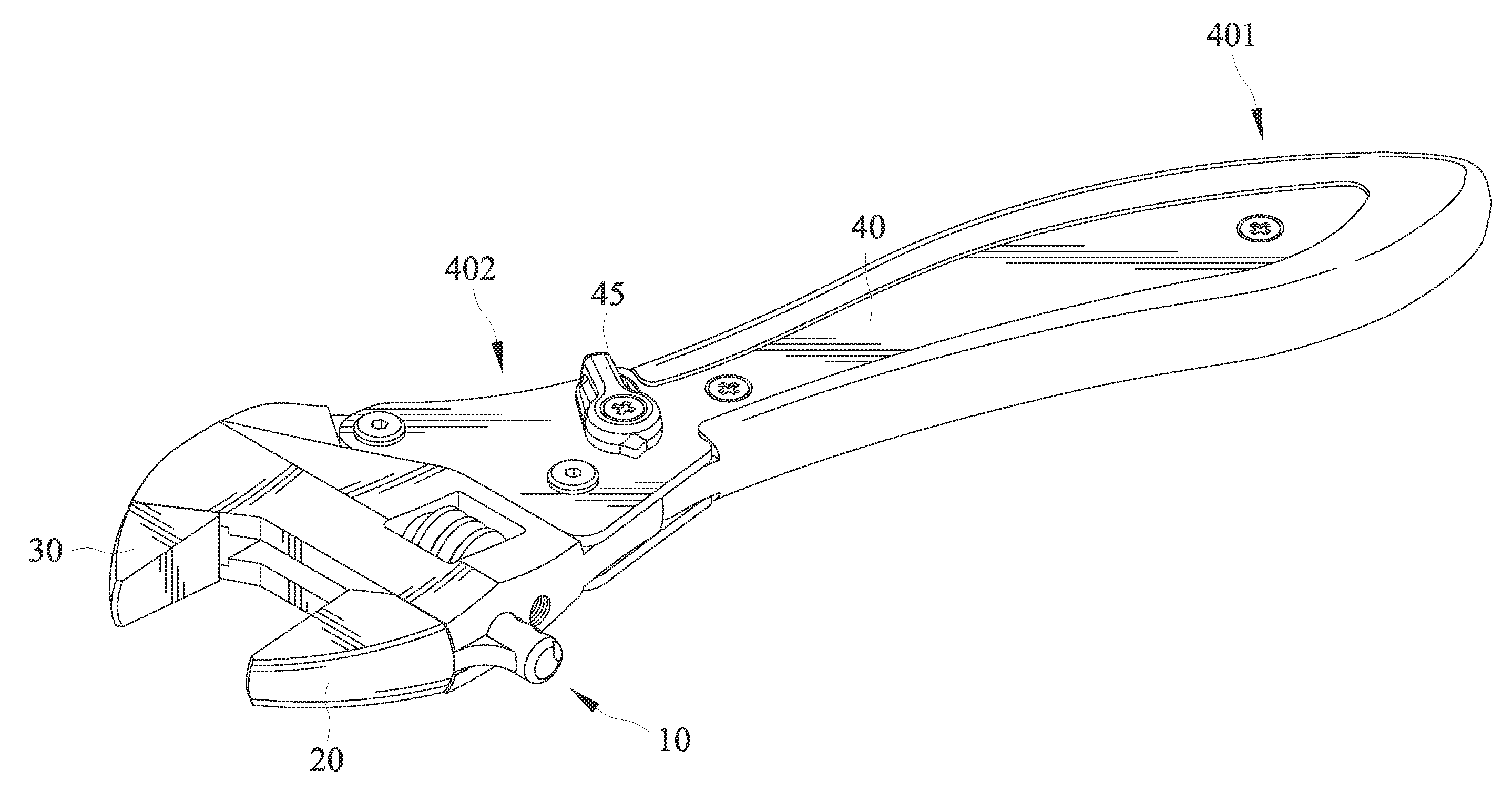
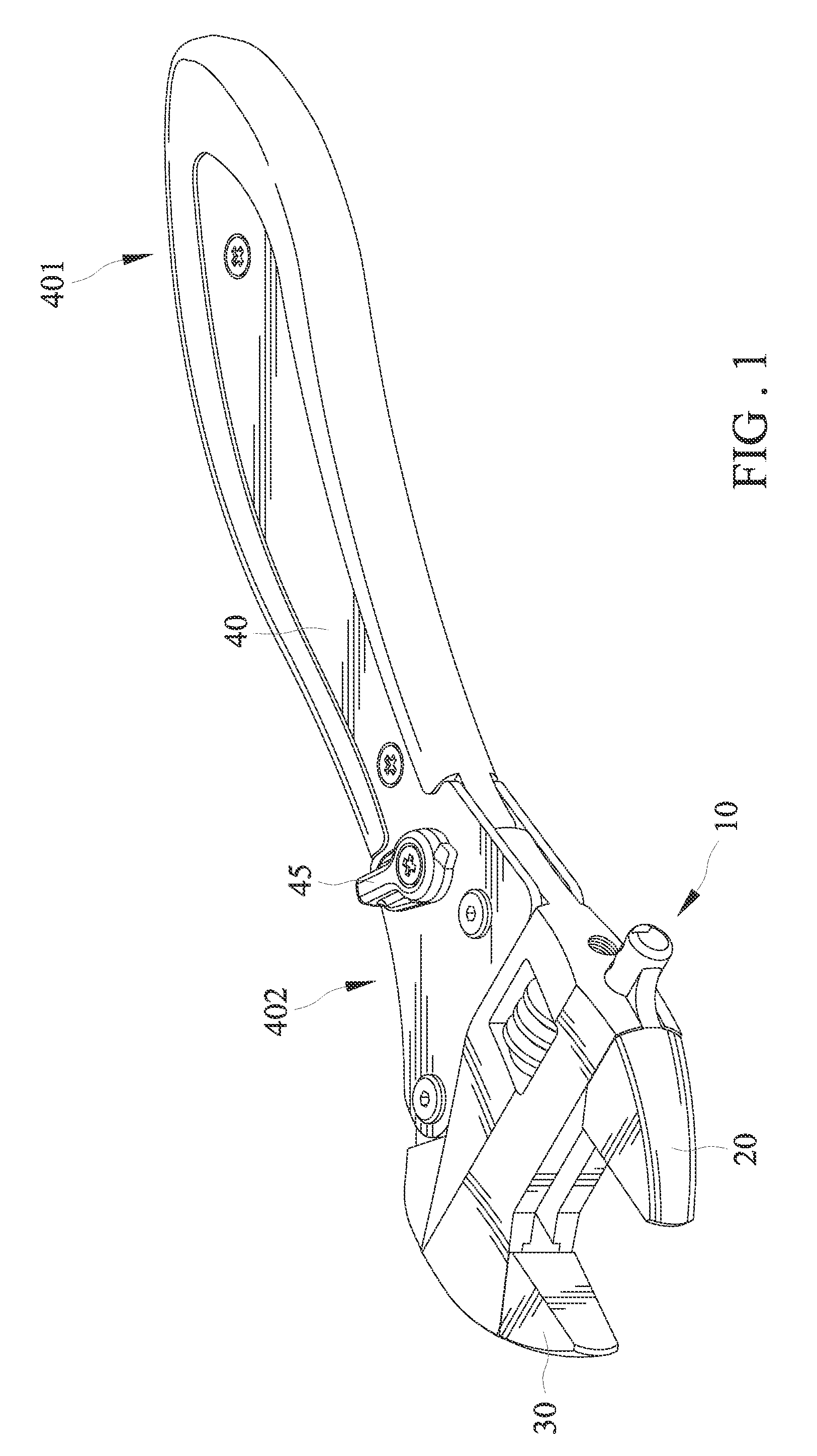
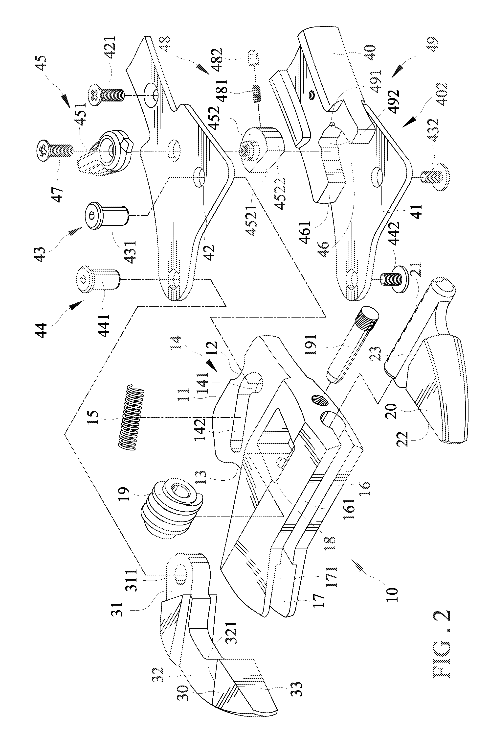
[0029]Referring to FIGS. 1 through 12, an adjustable spanner for quickly turning an object in accordance with a first embodiment of the present invention includes a moving member 10, a first jaw 20, a second jaw 30, and a grip 40.

[0030]The moving member 10 is movably joined to the grip 40 and comprises an end edge 11, a recess 12, a cavity 13, an elastic member 15, first and second guiding channels 16 and 17, a room 18, and a worm gear 19. The end edge 11 is defined on the outer periphery of the moving member 10 and extends in a length and provides a contact with the grip 40 when the adjustable spanner is in operation for turning an object “A”. The contact between the end edge 11 and the grip 40 allows the adjustable spanner to withstand a relatively large torque force imparted thereto. The end edge 11 and the grip 40 are in line contact with each other. The recess 12 is defined on an end edge 11. Likewise, the recess 12 is defined on the outer periphery of the moving member 10. The...


PUM


Abstract

An adjustable spanner for quickly turning an object includes a moving member, a first jaw, a second jaw, and a grip. The moving member is movably joined to the grip. The first jaw is adjustably jointed to the moving member. The second jaw is pivotally joined to the grip and cooperates with the first jaw to clamp the object. A user grasps the grip when using the adjustable spanner.

Description

BACKGROUND[0001]1. Field of the Invention[0002]The present invention relates to an adjustable spanner, and particularly, to an adjustable spanner for quickly turning an object.[0003]2. Description of the Related Art[0004]U.S. Pat. No. 6,336,384 shows an adjustable wrench for quickly turning an object. The adjustable wrench includes a main body, a slide block, a movable jaw and a grip. The main body includes a jaw section and a hollow section in which the slide block and the movable jaw are disposed. The grip is pivotally connected with the hollow section. A movable retaining block is disposed on one side of the top end of the grip and is opposite to a leaning section of the slide block. The retaining block can be switched, whereby when the grip is wrenched in different directions, the retaining block pushes the leaning section of the slide block so as to change the one-way wrenching direction of the adjustable wrench during repeated wrenching operation for an object. However, since ...

Claims


Application Information

Patent Timeline
Patent Type & Authority Patents(United States)
IPC IPC(8): B25B13/14B25B13/46B25B13/12
CPCB25B13/14B25B13/46B25B13/12B25B13/28
Inventor CHENG, KAI-WEI
Owner APEX BRANDS
Why Eureka
Try Eureka