Vehicle mirror support assembly with cast brace

a technology for supporting assemblies and mirrors, which is applied in the direction of machine supports, instruments, other domestic objects, etc., can solve the problems of disadvantageous weight, yoke, and not the best aerodynamic design of construction, and achieves the effects of improving structural strength, light weight, and satisfying stability

Inactive Publication Date: 2010-11-09
LANG MEKRA NORTH AMERICA LLC
View PDF12 Cites 0 Cited by
  • Summary
  • Abstract
  • Description
  • Claims
  • Application Information

AI Technical Summary

Benefits of technology

[0011]The above objectives are accomplished according to the present invention by the use of structural, mirror head support brace made by pressure casting (hereinafter referred to as “head braces”) instead of a simple metal tube, it becomes possible to add scorings or ribs to assure the exact positioning of a mirror head. Such a mounting can be carried out in only one operational step and include the manufacture of mirror support arms. An additional operational step is not necessary. The head brace is always fastened in the same way at the upper and lower support arms. In this way, the outer shape that is the cross-section of the head brace would always fit the mounting dimensions for a mirror head as well as meet the desired angular displacement. The design of the metal head brace assures a satisfactory stability.
[0012]Advantageously, a hollow structural member can be installed as the head brace whereby structural strength and stability can be increased.
[0013]Preferably the head brace will be composed of pressure cast aluminum since this is light in weight and possesses satisfactory structural strength. Moreover, corrosion preventive measures necessary for steel reinforcements can be avoided.
[0014]In accord with an advantageous embodiment, the pressure cast head brace, in tubular form, have at least one first longitudinal groove by means of which the head brace can assume a desired angular setting in relation to the upper and the lower support arms. In this way, the developed torque from the head brace and from its accompanying mirror head can be transferred to the support arms. Similarly, by means of this longitudinal groove, the angular position of the head brace in relation to the support arms can be predetermined. For an increase of the transferred torque, advantageously, two or more longitudinal grooves can be provided in the head brace. Because of the fact, that these longitudinal grooves do not lie rotationally symmetric to one another, the advantage is gained that the mirror head cannot be set at an erroneous angle upon mounting. Longitudinal grooves can be made easily in a head brace.
[0015]Advantageously, in at least one of the longitudinal grooves, a plurality of scorings running in the longitudinal direction is formed which, because of their side by side apportionment, permit an exact angular positioning of the of the mirror head. Because of a plurality of different angular positions of the mirror head which are attainable on the aluminum head brace and coupled with complementary projections to fit the scorings on the head brace, the angular placement of the mirror head can be made with great exactness.
[0016]By means of the symmetrical formation of the mirror support arms, the number of auxiliary components of an external mirror for a left and a right driven vehicle has been significantly reduced. Considering the vehicle mounting means for the upper and lower support arms, the pivotal points on the vehicle at these upper and lower mounts are positionally determined in such a manner that an equal separating distance is maintained and an equal angular opening is made between the upper and the lower support arms for each mirror head. Additionally, the left and right mirror heads are so fastened onto the mirror support arms, that between the upper fastening and the lower fastening, the same ratios are present, that is, a symmetrical arrangement has been achieved.

Problems solved by technology

Although the above designs are very stable and simple, they present a series of disadvantages.
The construction is not of the best aerodynamic design.
This disadvantage increases the danger of displacement during high wind exposure.
To prevent this, the yoke, when built for structural strength, disadvantageously becomes very heavy.
In addition, the furnishing of additional plastic anchor bolting brings about an unwanted plurality of individual parts.
This increases the cost of the manufacture of the mirror assembly and also increases expense for mounting.
Also, these modes of construction lead to a multiplicity of disadvantages namely, first, the mirror housings, which have been conceived for the above mentioned tubular yoke versions, are not affixed to a support arm.
Further, it is possible that the known housing having tubular yoke supports cannot be improved by upgrading to achieve an aerodynamically more favorable design with less air resistance.
Nor is it possible with such a support arm to enclose a mirror pane within a rim or a housing.
Moreover, the structural strength of the support arm, which is made completely of plastic, is so limited that a mirror affixed to a vehicle can be exceedingly damaged by vibrations due to wind or by vibrations emanating from the vehicle itself.
However, the attachment EP 1 531 084 B1 is of such a nature that it becomes impossible to use an identical support arm for installations on the right and left sides of a vehicle.
This now added part or parts increases not only the weight, manufacturing time, and mounting labor, but also introduces additional sources of vibration.
The direct costs of manufacture of various metal tubes when compared to a variant are possibly not greater, but the storage and logistic costs become excessive.
This leads to a considerably high construction cost and the danger of an erroneous assembly of the parts.

Method used


Image

  • Vehicle mirror support assembly with cast brace
  • Vehicle mirror support assembly with cast brace
  • Vehicle mirror support assembly with cast brace

Examples


Embodiment Construction

[0024]Referring now in more detail to the drawings, the invention will now be described in more detail.

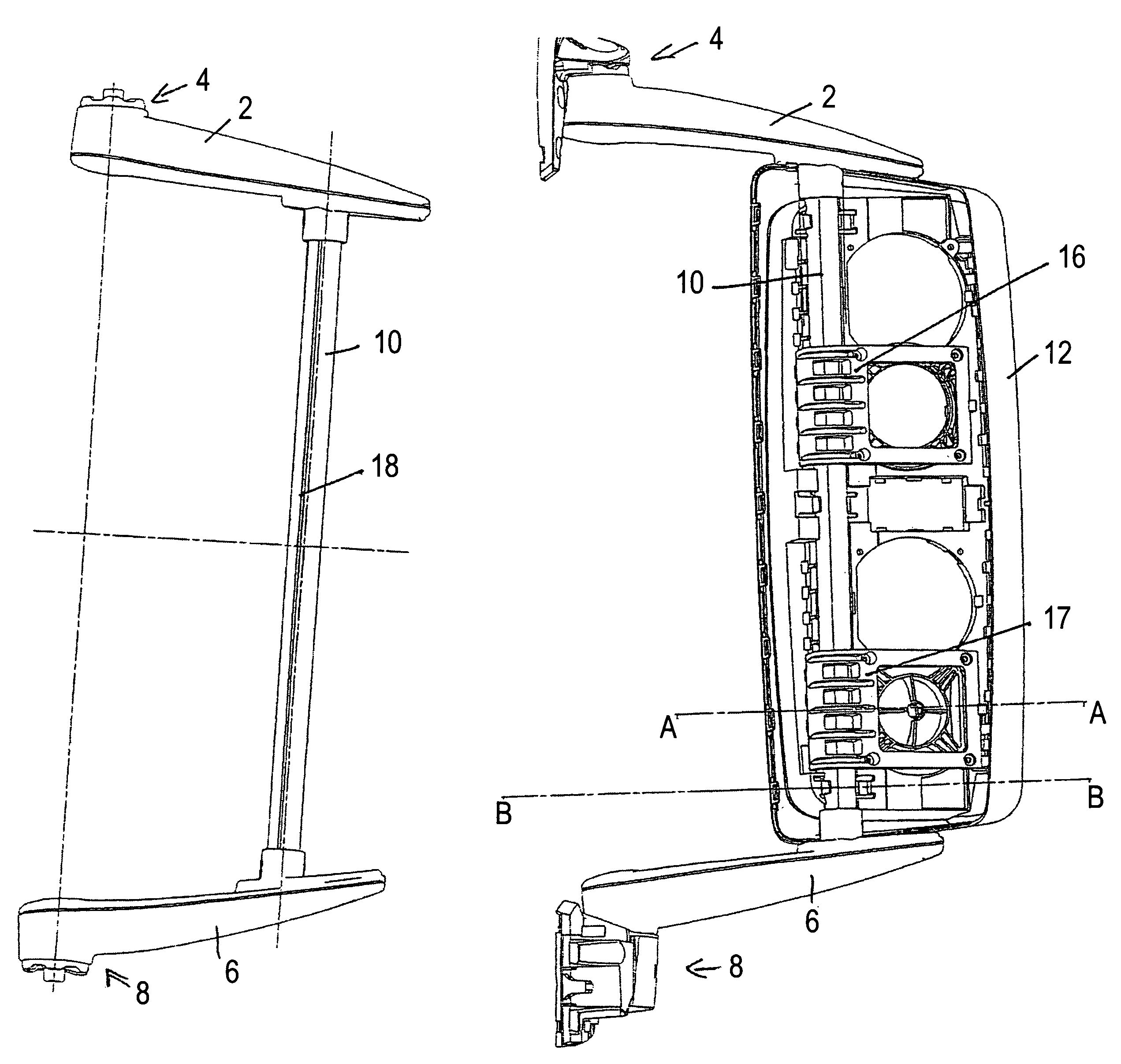
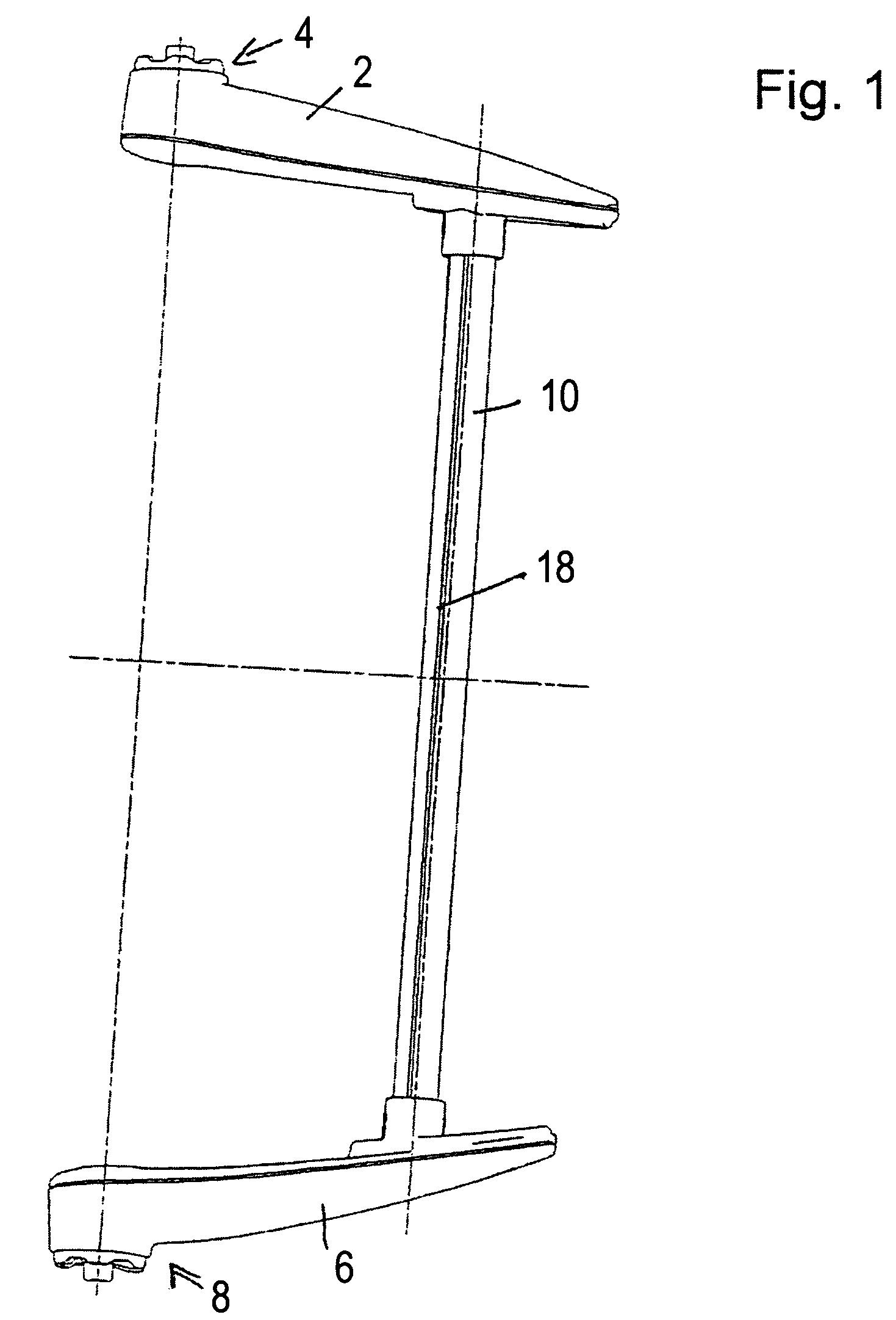
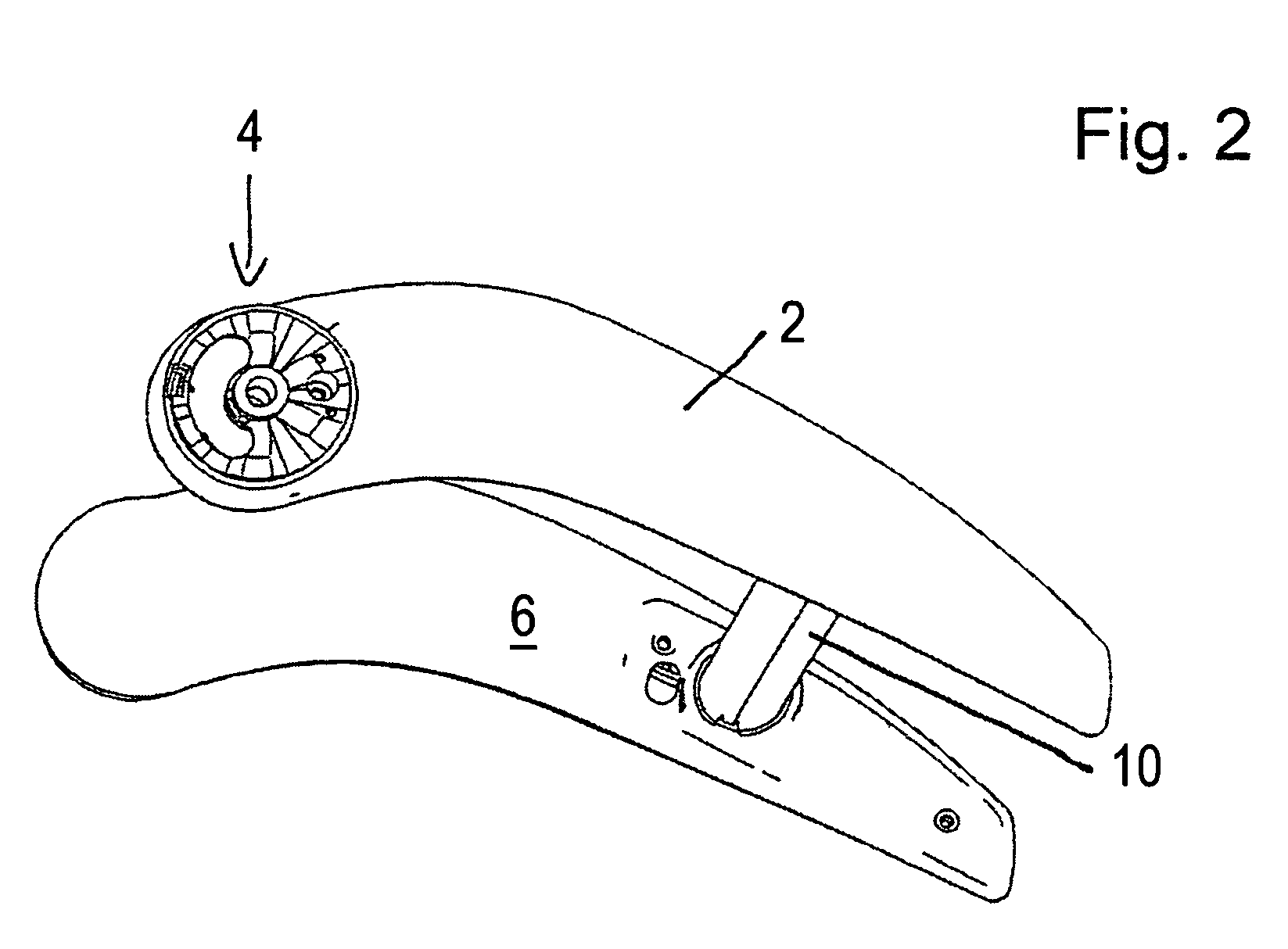
[0025]FIGS. 1 and 2 present, as viewed, left or right driven vehicle arrangements for a mirror support assembly, which include an upper support arm 2. Upper support arm 2 has on its end which contacts the vehicle body (not shown), an upper mounting element 4 for pivotally anchoring the upper support arm to the vehicle. Further, the upper mirror support arm 2 in FIGS. 1, 2 has a lower support arm 6 which, on its end, is proximal to the vehicle body (not shown) has, in like manner, a lower mounting element 8 for pivotally anchoring the lower arm to the vehicle body. The upper and the lower mounting elements 4, 8 are constructed as frictionally restrained, pivotal fixtures, parts of which are shown in the FIGS. 1 and 2.

[0026]The upper support arm 2 and the lower support arm 6 are united together by mirror head brace 10, which is hollow in design. This head brace, although tubular, is ...


PUM


Abstract

A mirror support assembly for a motor vehicle comprising an upper support arm, an upper mounting element for mounting the upper support arms to the vehicle, a lower support arm, and a lower mounting element for mounting the lower support arm to the vehicle. A mirror head brace for uniting the upper and lower support arms includes a cast structural member made by pressure casting. The mirror head brace includes at least one longitudinal groove which determines a defined angular setting between the mirror head brace and the upper and lower support arms. The plurality of scorings functionally determine different angular settings relative to the mirror support arms of a mirror head 12 which is carried by mirror head brace.

Description

BACKGROUND OF THE INVENTION[0001]This invention is directed to a support assembly for an outside mirror on a motor vehicle, especially for a commercial vehicle, and concerns additionally an outside mirror with such a support assembly.[0002]External, rear view mirrors for motor vehicles in accord with the state of the technology have at least one mirror head, which contains at least one mirror pane. Mirror panes of this kind can be placed rigidly or adjustably in a housing or can be directly affixed within a peripheral rim. Under certain circumstances the mirror housing can have an integral, motor operated adjustment for automatic angular positioning of the mirror pane in relation to the vertical and horizontal axes of the housing. Additionally, the external mirror may also possess heating elements for the warming of the mirror or be fitted with the like.[0003]In one simple variant, a mirror head is fastened by a U-shaped, tubular metallic yoke having two end fixtures which fit into ...

Claims


Application Information

Patent Timeline
Patent Type & Authority Patents(United States)
IPC IPC(8): G02B7/182
CPCB60R1/0605
Inventor MEIER, MARKUSPFANZ, JURGENPOPP, ALBRECHTDEFFNER, SIMON
Owner LANG MEKRA NORTH AMERICA LLC
Why Eureka
Try Eureka