Fixed seat for a tool

a technology for fixing seats and tools, which is applied in the field of fixed seats for tools, can solve the problems of affecting the locating robustness of the sleeves and the allowed big mating errors, and achieve the effects of reducing the number of mating errors, facilitating the locating of the sleeves, and facilitating the assembling of the sleeves

Active Publication Date: 2013-08-06
HSIEH CHIH CHIEN
View PDF11 Cites 14 Cited by
  • Summary
  • Abstract
  • Description
  • Claims
  • Application Information

AI Technical Summary

Benefits of technology

[0013]Based on the unique structural configuration of the present invention wherein the “fixed seat for tool” mainly comprises: a sleeve joint pillar with abutment surface and edge or margin part, positioning convex parts and lateral through-holes, a novel fixed seat for tool is adopted for locating sleeve by means of rotary fastening. The sleeve is rotated in such a manner that the positioning concave camber of the square casing groove is interlocked with the positioning convex part of the sleeve joint pillar, so the positioning convex part presents retraction flexibility when a flexible wall rim is formed with the arrangement of the lateral through-hole. Hence, a bigger mating error is allowed between the sleeve's square casing groove and sleeve joint pillar without affecting the locating robustness of the sleeve. Moreover, this enables to fetch and assemble the sleeve more smoothly, and also improves its locating robustness and operational convenience. On the other hand, with the arrangement of said lateral through-hole, the positioning convex part can be retracted flexibly, so the present invention features simple structure and ease of manufacturing while maintaining satisfactory structural strength of the sleeve joint pillar.

Problems solved by technology

Hence, a bigger mating error is allowed between the sleeve's square casing groove and sleeve joint pillar without affecting the locating robustness of the sleeve.

Method used


Image

  • Fixed seat for a tool
  • Fixed seat for a tool
  • Fixed seat for a tool

Examples


Embodiment Construction

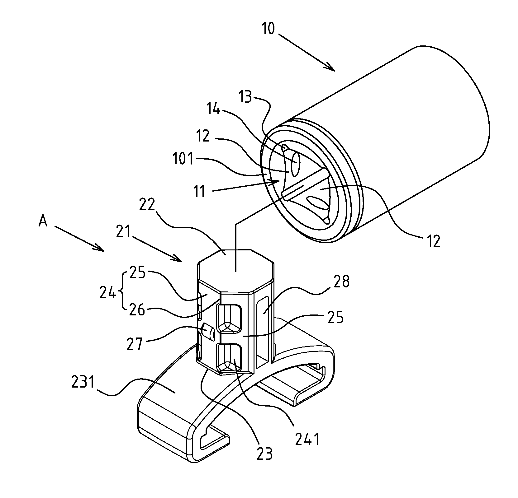
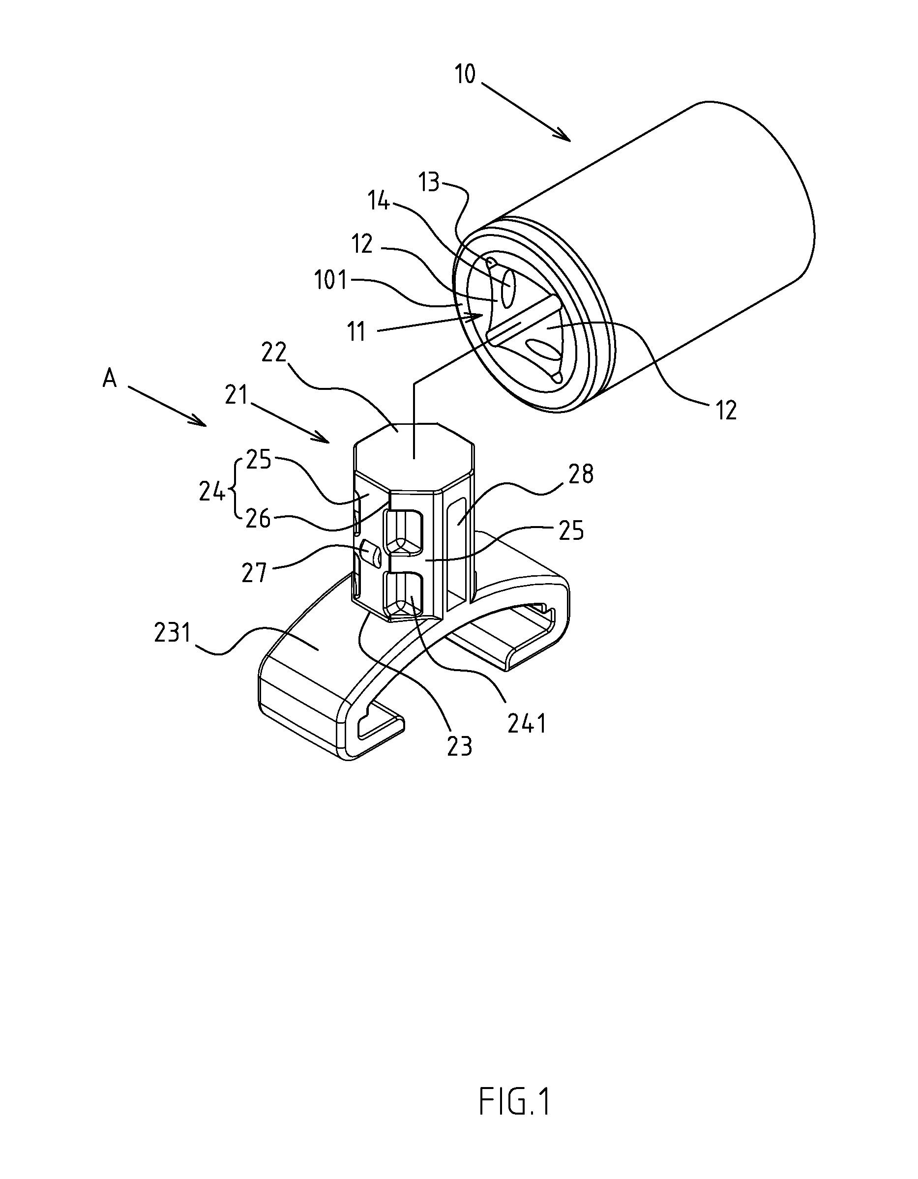
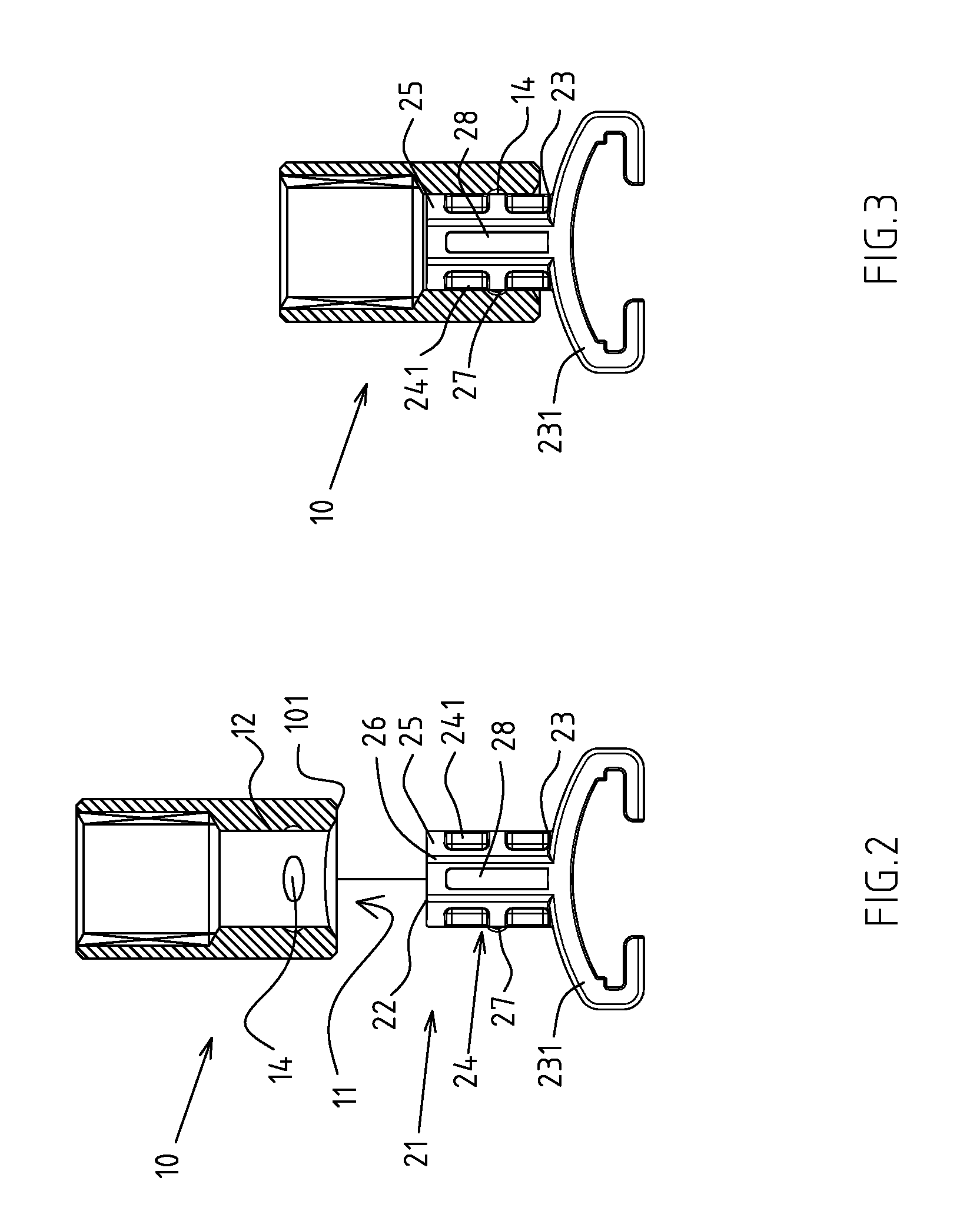
[0025]FIGS. 1-7 depict preferred embodiments of a fixed seat of the present invention, which, however, are provided for only explanatory objective for patent claims. Said fixed seat for a tool A is exclusively used for setting and locating the sleeve 10 (including customized and non-customized specifications) by rotary fastening. The toolkit side 101 of said sleeve 10 is provided with a square casing groove 11 to define four groove walls 12 and edges 13 set between the groove walls 12. A positioning concave camber 14 is set deeply onto at least a groove wall 12.

[0026]The fixed seat for tool A comprises a sleeve joint pillar 21, set into a polygonized pillar to define a top side 22, a under side 23 and circumference side part 24, of which the circumference side part 24 contains a few abutment surfaces 25 and convex corners 26 formed between the abutment surfaces 25. Said abutment surface 25 can be abutted onto the groove wall 12 of the square casing groove 11 on the toolkit side 101 ...


PUM


Abstract

A fixed seat for a tool has a sleeve joint pillar set into a polygonized pillar, of which the circumference side part contains abutment surfaces and edges. The abutment surface can abut the groove wall of the sleeve's square casing groove, and said edge or margin part permits spanwise locking of the sleeve during its rotation. A positioning convex part is protruded from an abutment surface on the circumference side part of the sleeve joint pillar, and interlocked with the positioning concave camber on the groove wall of the square casing groove. A lateral through-hole is set onto one side of the sleeve joint pillar. Both ends of the lateral through-hole pass through separately the abutment surface on the circumference side part of the sleeve joint pillar. A wall rim is formed between the abutment surface and the lateral through-hole, so that the positioning convex part could be squeezed flexibly.

Description

CROSS-REFERENCE TO RELATED U.S. APPLICATIONS[0001]Not applicable.STATEMENT REGARDING FEDERALLY SPONSORED RESEARCH OR DEVELOPMENT[0002]Not applicable.NAMES OF PARTIES TO A JOINT RESEARCH AGREEMENT[0003]Not applicable.REFERENCE TO AN APPENDIX SUBMITTED ON COMPACT DISC[0004]Not applicable.BACKGROUND OF THE INVENTION[0005]1. Field of the Invention[0006]The present invention relates generally to a fixed seat for a tool, and more particularly to an innovative one which permits location of the sleeve by means of rotary fastening.[0007]2. Description of Related Art Including Information Disclosed Under 37 CFR 1.97 and 37 CFR 1.98.[0008]The fixed seat for a tool referred to herein is an auxiliary seat for locating a sleeve. The configuration of such fixed seat may vary from different sleeves, e.g.: single- or multiple-piece arrangement with use of lifting subs or retaining frames.[0009]Said fixed seat for a tool is structurally configured in a way that a square pillar is generally protruded ...

Claims


Application Information

Patent Timeline
Patent Type & Authority Patents(United States)
IPC IPC(8): B65D73/00
CPCB25H3/04
Inventor HSIEH, CHIH-CHIEN
Owner HSIEH CHIH CHIEN
Why Eureka
Try Eureka