Method and device for controlling a hydraulic actuator

a technology of hydraulic actuators and actuators, applied in electrical control, non-mechanical valves, machines/engines, etc., can solve the problems of high modeling and/or application expenditure in order to achieve the required actuator precision, rapid change, and difficult modeling, so as to avoid transient errors of valve lift, high actuator precision, and large possible errors

Inactive Publication Date: 2009-01-15
ROBERT BOSCH GMBH
View PDF16 Cites 28 Cited by
  • Summary
  • Abstract
  • Description
  • Claims
  • Application Information

AI Technical Summary

Benefits of technology

[0017]An object of the present invention is to provide a valve-lift control, improved on the basis of a positioning-travel feedback, which ensures the required high actuator precision even in the event of highly dynamic changes of influence variables and large possible errors in determining such influence variables, and in particular, avoids transient errors of the set valve lift.

Problems solved by technology

A general disadvantage of these conventional design approaches is that they have to rely on a very good prediction of the possible actuator progressions, and therefore involve a high modeling and / or application expenditure in order to achieve the required actuator precision.
In part, they are rapidly changeable, such as the oil pressure, and / or are difficult to model, like the gas forces, for instance.
In the case of the EHVC system indicated, the basic requirement for a practical application or transfer of the conventional design approaches, i.e., for a regulation of the movement characteristic is not fulfilled, since a proportional driving and therefore producible positioning-force regulation is not possible as a matter of principle.
In addition, errors in determining influence variables are not or are scarcely offset by an adaptation, and are only partially offset by a cycle-based regulation.
Therefore, in spite of available feedback about the adjusted lifts, rapid changes of influence variables such as the oil pressure or of setpoint values of individual valve parameters almost unavoidably lead to noticeable transient setpoint / actual deviations of the valve lift.
Therefore, the feedback about the movement characteristic also contains no information whatsoever about an implemented correction of the driving, since this correction really does not become effective immediately, but only at the end.
Such large errors may occur, for example, in an operating state with high performance demand on the engine in the event of a combustion miss, thus, given the almost complete omission of a normally expected gas force to be kept high at an exhaust valve, if the driving time of the exhaust valve calculated for the normal case is not corrected.
In the design approach presently described, such circumstances are corrected automatically, since the faster opening of the exhaust valve leads to a corresponding (sharp) shortening of the driving time.

Method used


Image

  • Method and device for controlling a hydraulic actuator
  • Method and device for controlling a hydraulic actuator
  • Method and device for controlling a hydraulic actuator

Examples


Embodiment Construction

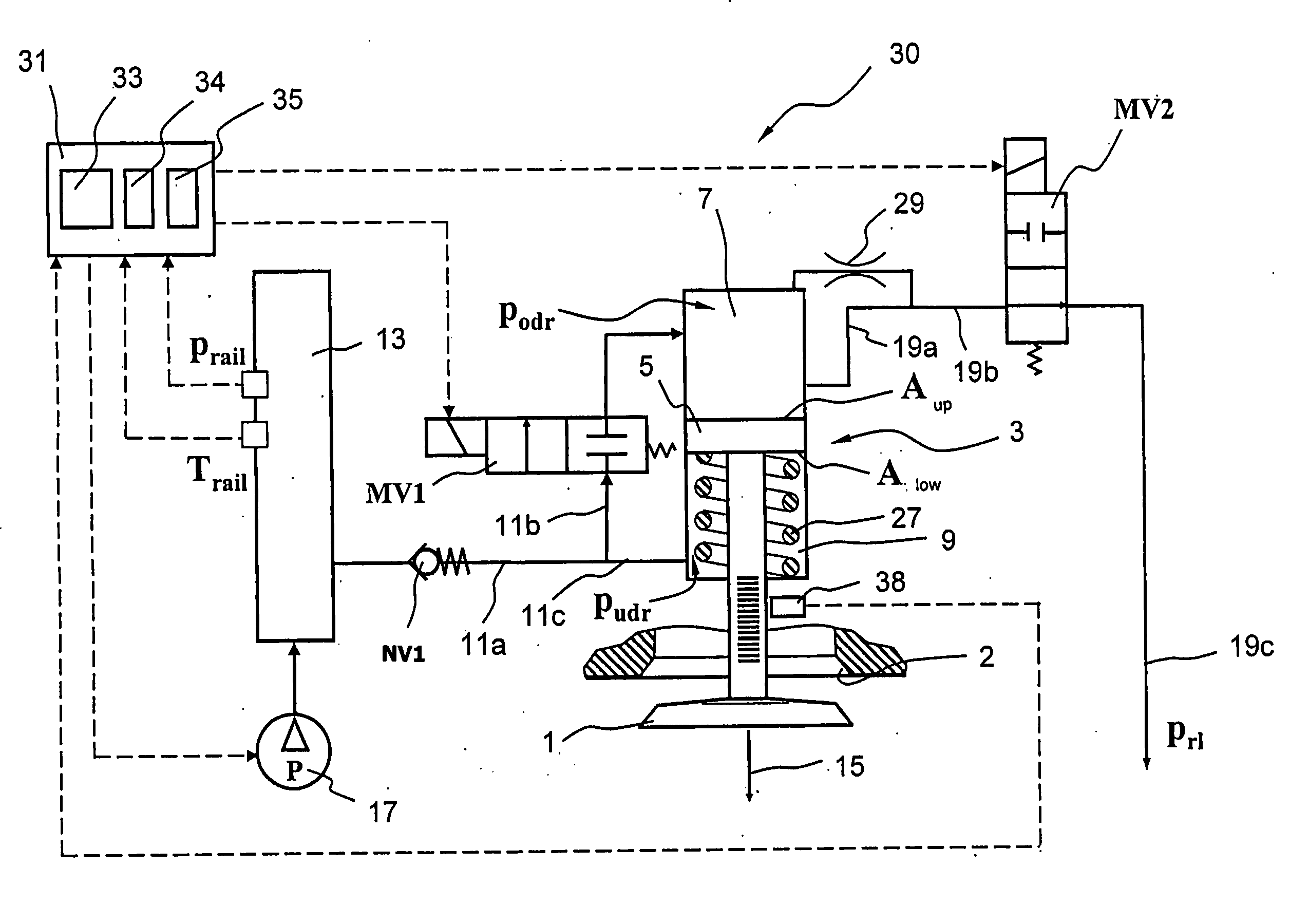
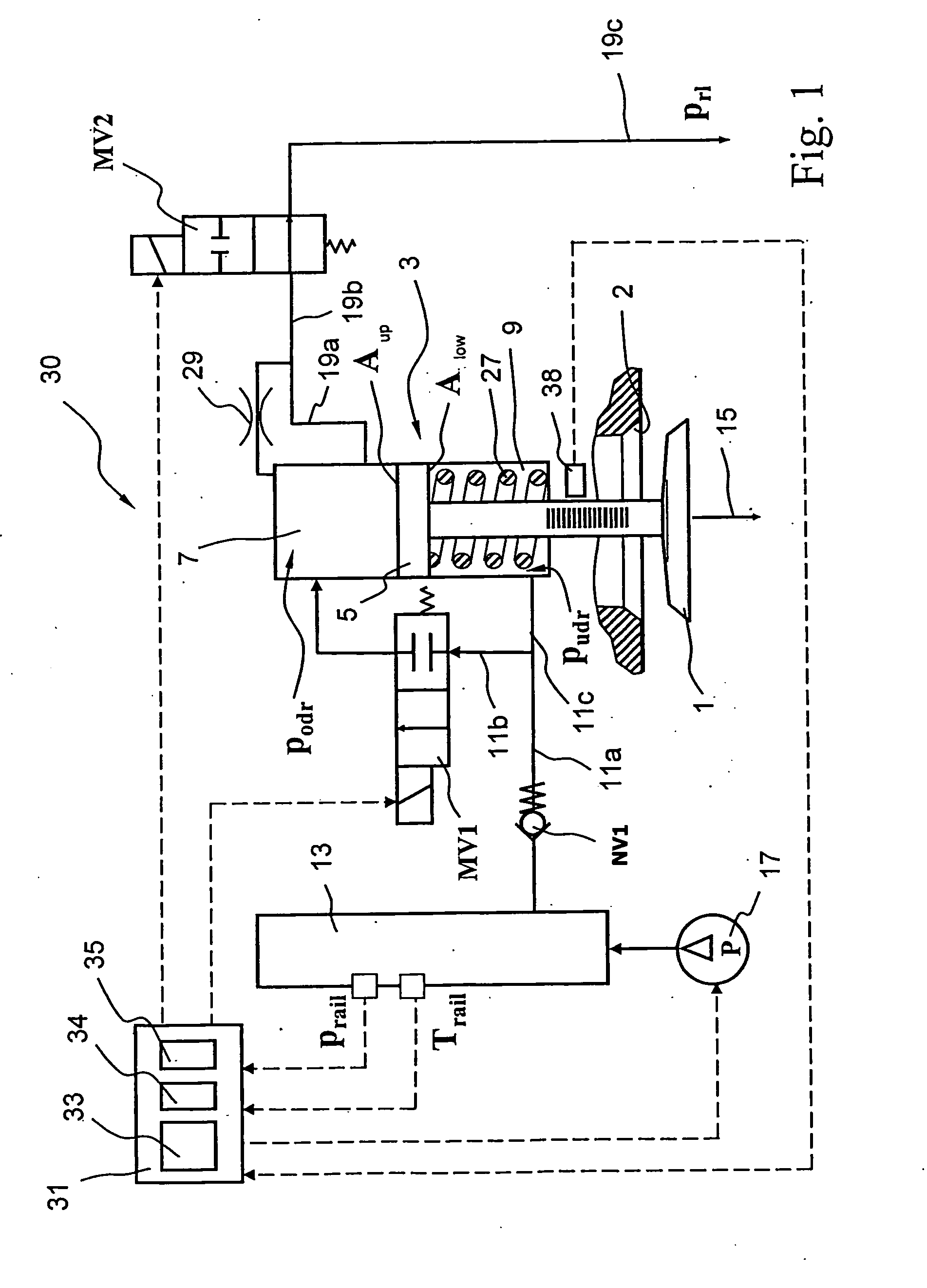
[0066]FIG. 1 shows schematically a conventional exemplary embodiment of an electrohydraulic valve control (EHVC), based on which the control method according to the present invention is intended to be carried out. However, the present invention is not restricted to this exemplary use.

[0067]Actuator 30 shown in FIG. 1 is used by way of example for actuating a gas-exchange valve (GEV) 1 of an internal combustion engine. Gas-exchange valve 1 may be implemented as an intake valve or exhaust valve. In the closed state, it rests on a valve seat 2.

[0068]Instead of a single gas-exchange valve 1, in elaboration of the arrangement sketched in FIG. 1, a pair of interconnected gas-exchange valves (double-acting valve) may also be actuated together, in particular may be synchronously opened and closed, by a single hydraulic actuator. Hereinafter, when a gas-exchange valve 1 is mentioned, a double-acting valve along the lines of this expanded arrangement can always be meant, as well.

[0069]Gas-exc...


PUM


Abstract

A method, device, and control unit for controlling an actuator in open loop, particularly for a valve, preferably for a gas-exchange valve of an internal combustion engine, having at least one control valve for opening the valve and one control valve for closing the valve, each of the control valves being capable of being driven by at least one drive pulse whose duration determines a position on the positioning travel of the valve. The valve is opened/closed in one lift and/or a plurality of partial lifts and at least one drive pulse is assigned to each lift and/or each partial lift, and the valve is assigned at least one transducer which generates a signal that discloses values of a discrete positioning travel of the valve and of an assigned time and/or of a discrete instant and of an assigned positioning travel. The method for controlling the actuator includes:
a. Starting of a drive pulse having a setpoint duration of the drive pulse for opening and/or closing the valve,
b. Generating at least one signal, and
c. Correcting the setpoint duration of the drive pulse and/or of a following drive pulse assigned to the lift and/or to a partial lift, in accordance with the signal.

Description

CROSS REFERENCE[0001]This application claims benefit under 35 U.S.C. § 119 of German Patent Application No. 102007025619.3, filed no Jun. 1, 2007, which is expressly incorporated herein by reference in its entirety.FIELD OF THE INVENTION[0002]The present invention relates to a method for controlling an actuator in open loop, particularly for a valve, preferably for a gas-exchange valve of an internal combustion engine, having at least one control valve for opening the valve and one control valve for closing the valve, each of the control valves being capable of being driven by at least one drive pulse whose duration determines a position on the positioning travel of the valve. The present invention further relates to a corresponding device and a corresponding control unit.BACKGROUND INFORMATION[0003]Conventional methods of this kind for controlling an actuator, particularly for hydraulic actuators of the type indicated at the outset, are used for actuating valves such as the gas-exc...

Claims


Application Information

Patent Timeline
Patent Type & Authority Applications(United States)
IPC IPC(8): F16K31/02F01L9/02F01L9/10
CPCF01L9/02F01L2800/00F02D2041/001F01L2820/045F02D41/20F01L2800/09F01L9/10
Inventor SCHIEMANN, JUERGEN
Owner ROBERT BOSCH GMBH
Why Eureka
Try Eureka