Method and apparatus for variable refrigerant chiller operation

a variable refrigerant chiller and operation method technology, which is applied in the direction of domestic cooling apparatus, lighting and heating apparatus, and cooling fluid circulation, etc., can solve the problems of less refrigerant being available to the chiller system, changing the heat transfer characteristics of the evaporator, etc., to reduce the pressure of the compressor head, reduce the load condition, and avoid surge conditions

Active Publication Date: 2015-12-22
JOHNSON CONTROLS TYCO IP HLDG LLP
View PDF34 Cites 10 Cited by
  • Summary
  • Abstract
  • Description
  • Claims
  • Application Information

AI Technical Summary

Benefits of technology

[0013]Efficient operation of multiple chillers with VSD drives indicates that operating several chillers at part load is more efficient than operating fewer chillers at full load. Running a chiller at part load limits the RPM of the VSD (generally 30 Hz), which results in the chiller generally running at a lower load condition. When the chiller unit is running at a lower load condition, the chiller unit is more likely or may have a tendency to surge. Surging should be avoided and this system removes additional refrigerant from the chiller system when the additional cooling capacity is not needed, thereby assisting in avoiding surge conditions. Adding refrigerant will decrease compressor head pressure and increase volume flow rate which helps avoid surge at a given RPM speed.
[0014]An advantage of the present disclosure is that it can be utilized to reduce the number of chiller geometrical variations required to support different load conditions. Another advantage is that by varying the amount of refrigerant and subsequently the heat transfer characteristics, operation of the chiller can be maintained with potentially lower building loads.
[0015]A further advantage is seasonal deployment of the variable refrigerant system (3-4 months frequency). During summer months when a fuller load operation is desired, less refrigerant will be deployed into the chiller system. During the fall / spring a portion of the refrigerant will be stored in the refrigerant vessel and in the winter the refrigerant in the refrigerant vessel will decrease to support part load and avoid surge in low load scenarios.
[0016]A further advantage of the present disclosure is that it provides a greater efficiency of chiller operation at part load, thus providing a secondary method to prevent surge or control against surge in the system.
[0017]Still a further advantage of the present disclosure is that it provides for a significant annualized energy efficiency improvement over current HVAC systems.

Problems solved by technology

This method will result in less refrigerant being available to the chiller system and also changes the heat transfer characteristics in the evaporator.

Method used


Image

  • Method and apparatus for variable refrigerant chiller operation
  • Method and apparatus for variable refrigerant chiller operation
  • Method and apparatus for variable refrigerant chiller operation

Examples


Embodiment Construction

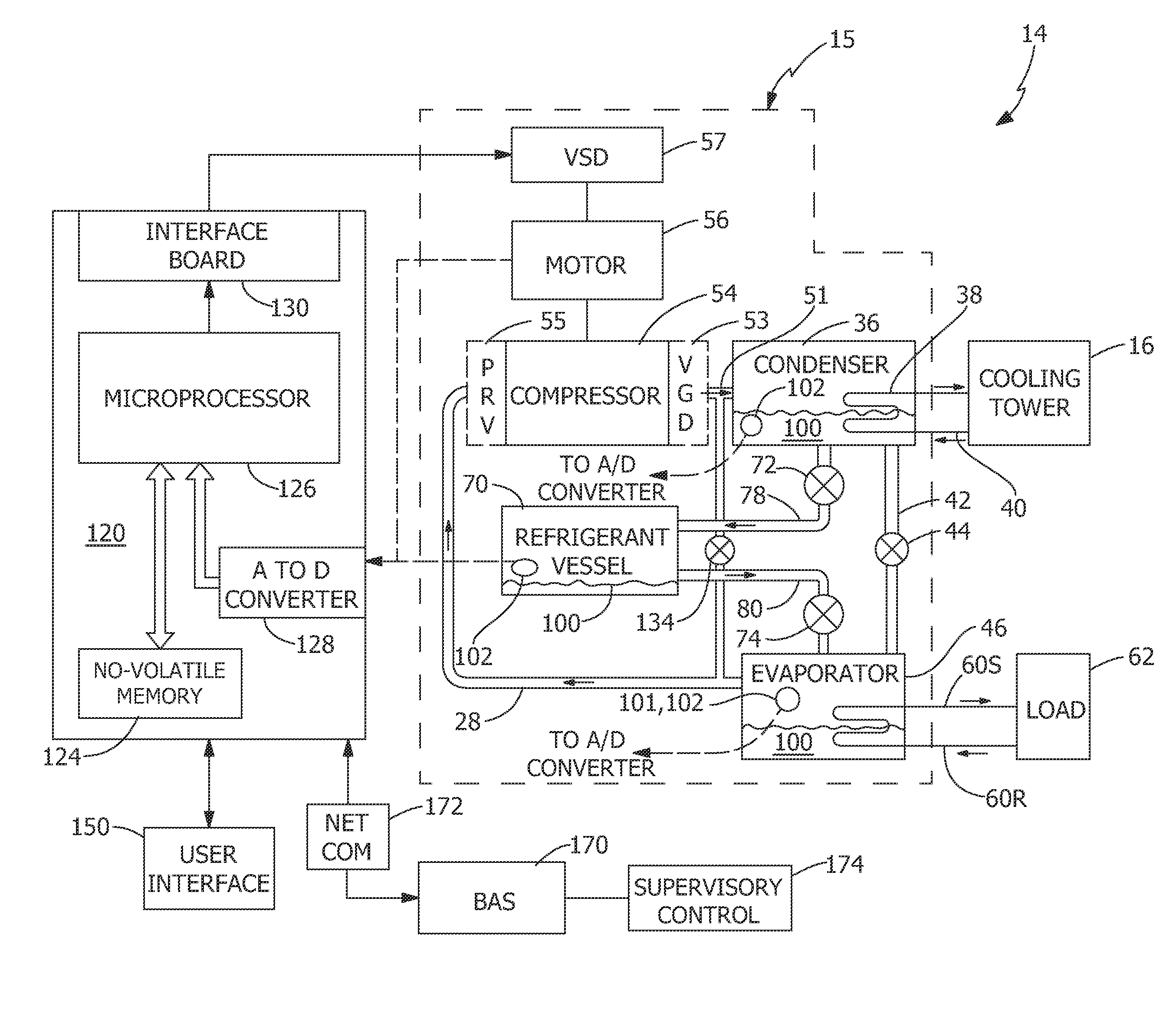
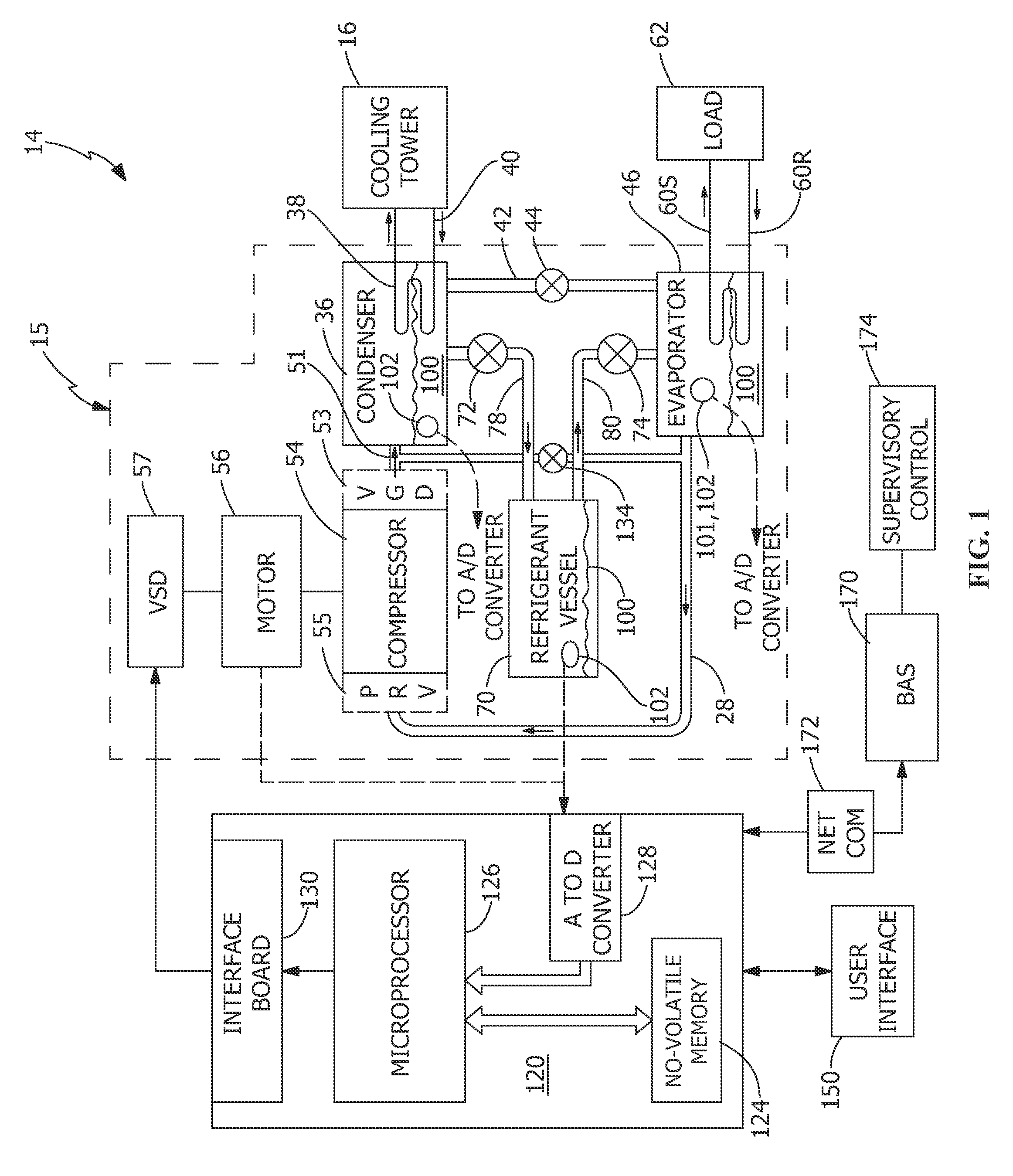
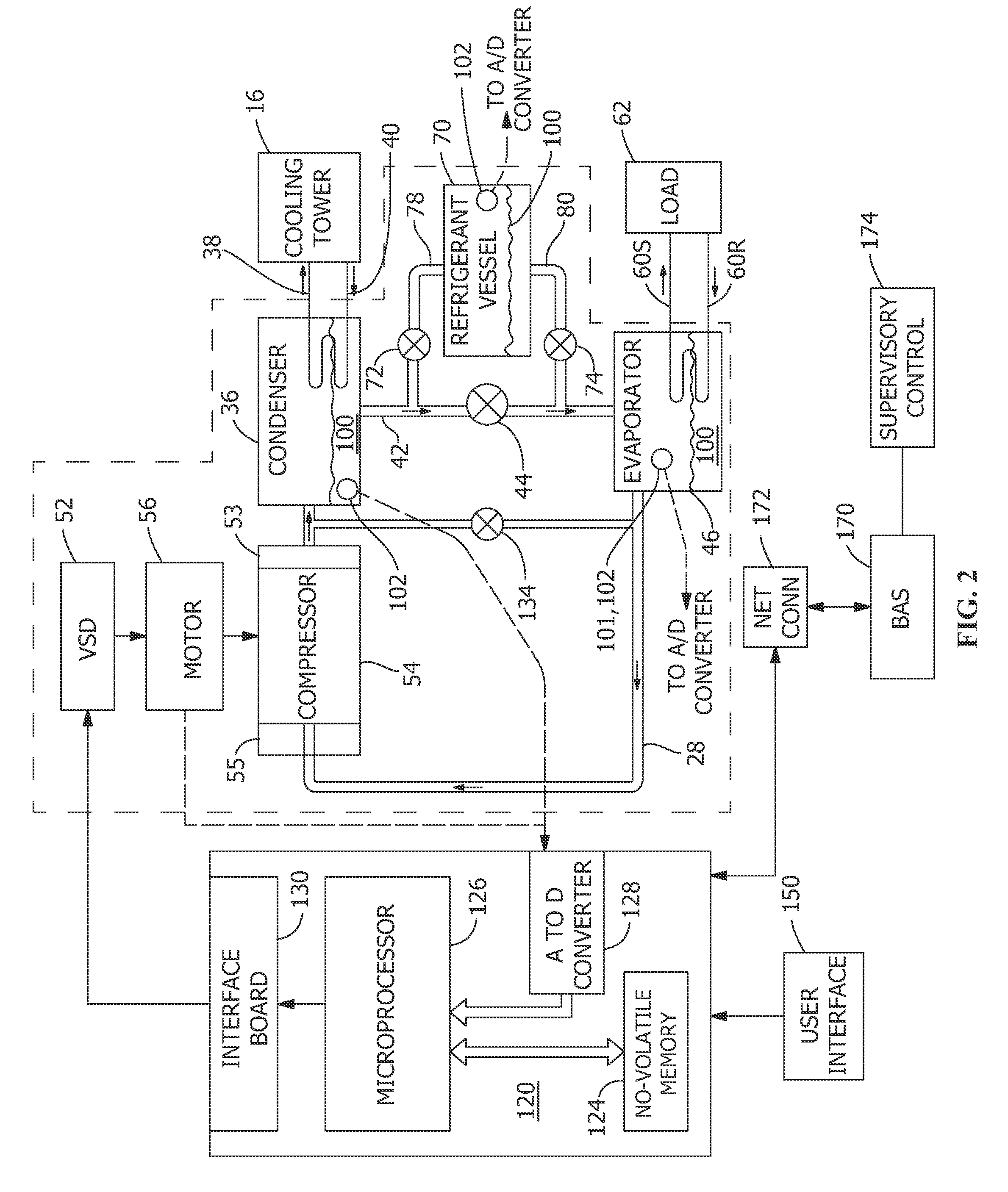
[0028]FIG. 1 depicts a Heating, Ventilating, and Air Conditioning (HVAC) system 10 that is typically installed in a building (not shown). The HVAC system 10 includes a cooling tower 16 positioned on the roof of the building. In an exemplary embodiment, cooling tower water is supplied to cooling tower 16 from a condenser 36 by a cooling tower supply line 38, and cooling tower return water is returned to condenser 36 by cooling tower return line 40. Condenser 36 is also connected to an evaporator 46, and to a refrigerant vessel 70, the operation of which is discussed in detail below. Refrigerant circulates as a gas from a compressor 54, driven by a motor 56 through refrigerant line 58 to condenser 36 where it undergoes a change of state and is condensed to a liquid. Although compressor 54 is depicted as a single compressor, a closed-loop chiller system 15 may include a plurality of compressors 54 operating in series, in which refrigerant gas flows from a first compressor to a second c...


PUM


Abstract

A refrigeration system includes a compressor, a condenser, an expansion device, an evaporator, and an additional refrigerant vessel connected in a closed refrigerant loop. The additional refrigerant vessel is connected to the condenser at the high pressure side by a first valve and to the evaporator at a low pressure side by a second valve. A controller controls operation of the first valve and the second valve. Only one of the first valve and the second valve may be open at the same time. Refrigerant from the additional refrigerant vessel may be added to the closed refrigerant loop when the controller receives a low refrigerant level indication of in the evaporator. Refrigerant may also be removed from the closed refrigerant loop when the controller receives a high refrigerant level indication in the evaporator.

Description

CROSS-REFERENCE TO RELATED APPLICATIONS[0001]This application claims the benefit of U.S. Provisional Application No. 61 / 414,681 entitled “METHOD AND APPARATUS FOR VARIABLE REFRIGERANT CHILLER OPERATION” filed Nov. 17, 2010, which application is hereby incorporated by reference in its entirety.BACKGROUND[0002]The present disclosure is directed to a method and apparatus for more efficient operation of a refrigeration system. More particularly, the disclosure relates to a method and apparatus for more efficient operation of a variable refrigerant chiller in the refrigeration system, which includes an additional refrigerant vessel to allow for variation of the amount of refrigerant in the refrigeration system.[0003]Conventional chilled liquid systems in vapor compression refrigeration systems used in heating, ventilation and air conditioning systems include a condenser vessel, an evaporator vessel, a compressor, a variable speed drive (VSD), an expansion valve, and optionally a hot gas ...

Claims


Application Information

Patent Timeline
Patent Type & Authority Patents(United States)
IPC IPC(8): F25B45/00F25D17/02F25B1/00
CPCF25B45/00F25B2700/04F25B2500/19
Inventor TURNEY, ROBERT D.KAUFFMAN, JUSTIN P.DREES, KIRK H.NOBOA, HOMEROLENHARDT, BRETT M.
Owner JOHNSON CONTROLS TYCO IP HLDG LLP
Why Eureka
Try Eureka