Electric highway system

a technology of electric highways and electric cables, applied in the direction of cables installed in underground tubes, rail devices, instruments, etc., can solve the problems of increasing the cost of construction, increasing the time consumption, and not being able to meet the needs of high-speed operations, so as to achieve the effect of easy detection and repair and convenient repair

Inactive Publication Date: 2011-04-28
SAKITA MASAMI
View PDF5 Cites 24 Cited by
  • Summary
  • Abstract
  • Description
  • Claims
  • Application Information

AI Technical Summary

Benefits of technology

[0006]An object of this invention is the provision of an electric highway system that is least costly to build, not susceptible to failures, and if failures occur, can be easily detected and repaired. In order to achieve the object, the induction power transfer s...

Problems solved by technology

This current collection method, however, is neither designed for high speed operations nor applicable to the ordinary automobile.
The electromagnetic induction power transfer technology, however, pr...

Method used


Image

  • Electric highway system
  • Electric highway system
  • Electric highway system

Examples


embodiment

Preferred Embodiment

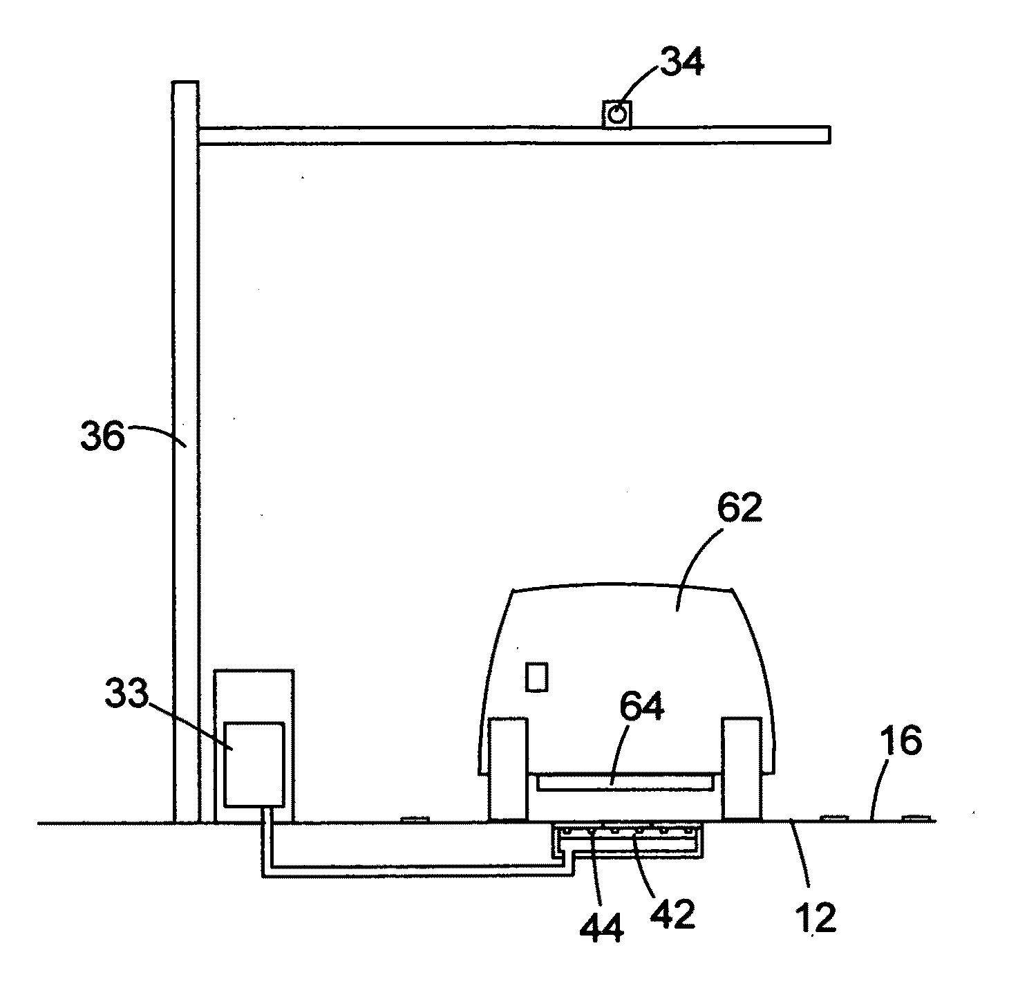
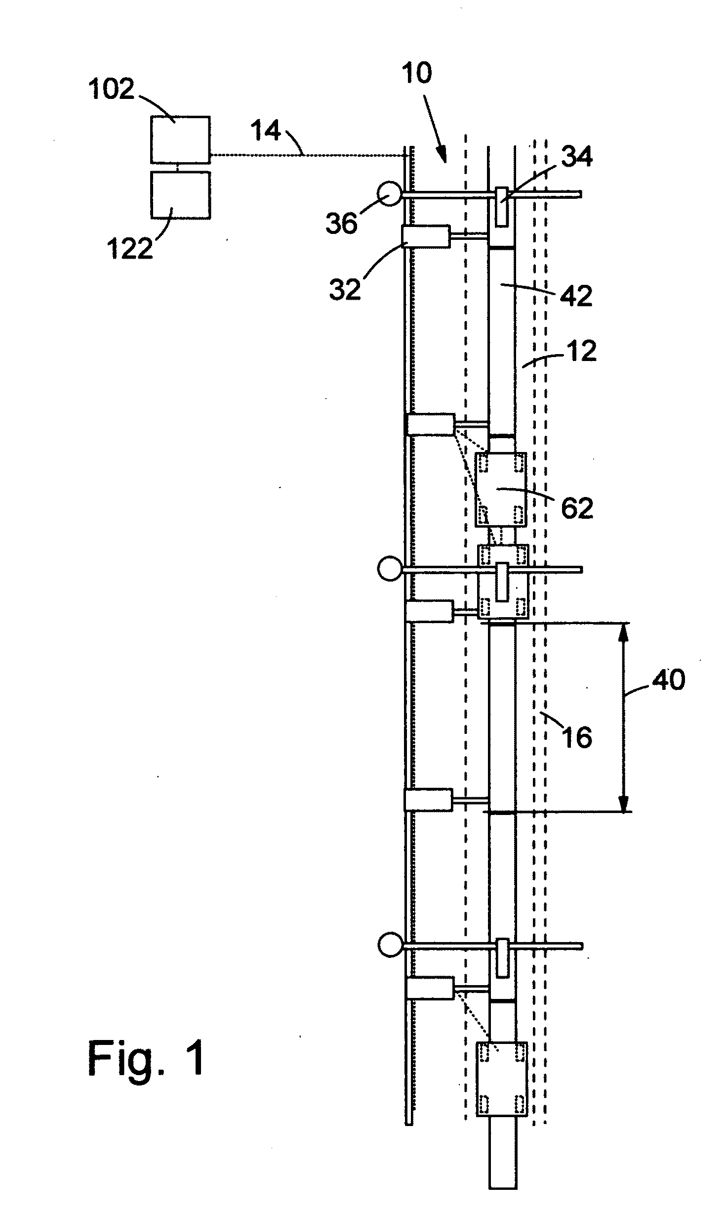
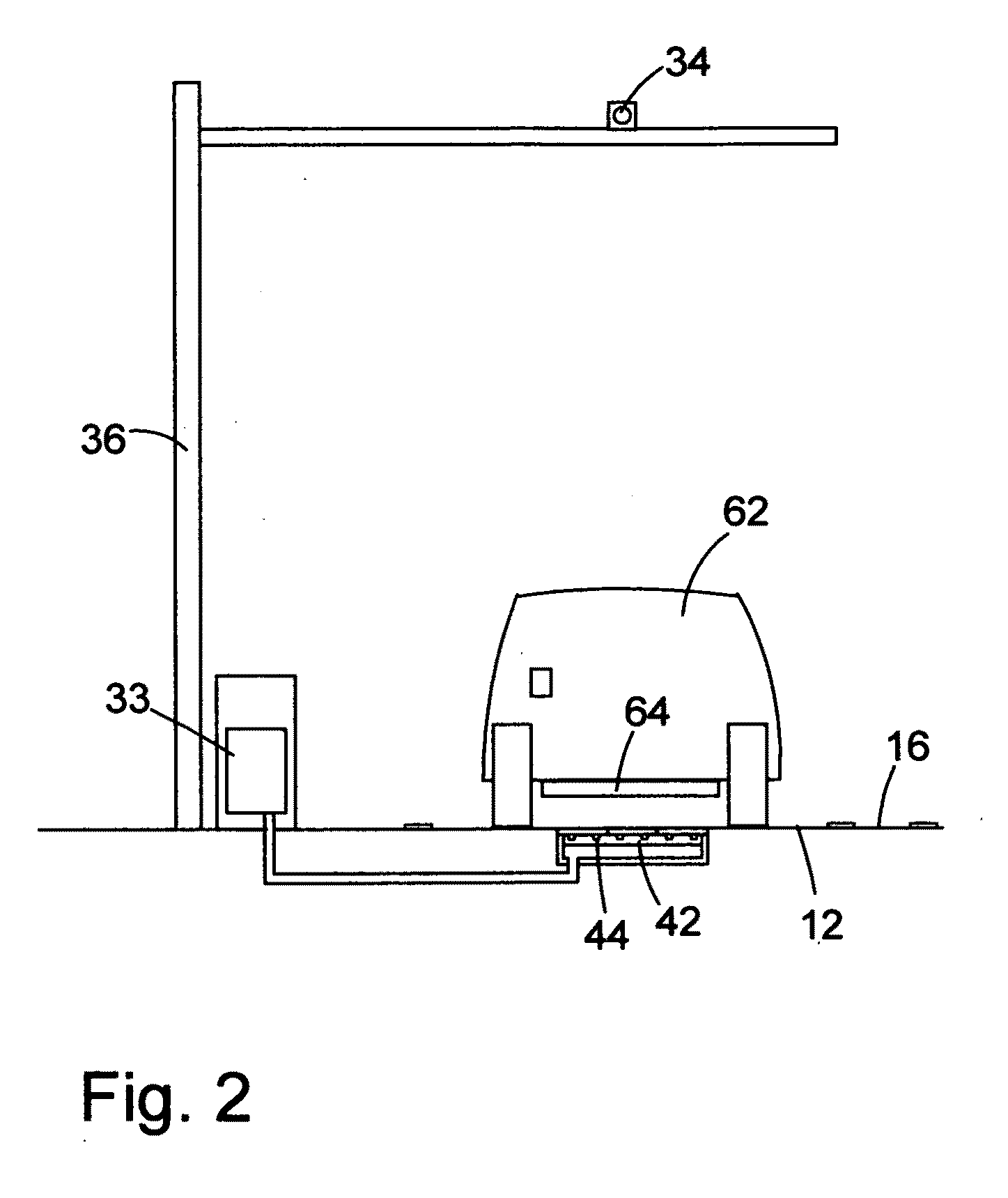
[0026]As shown in FIGS. 1 and 2, the preferred embodiment of the electric highway system of present invention includes a roadside subsystem 10; a centralized system operation monitoring center 102 and an account processing center 122 that may be located in the same facility as the system operation monitoring center; a communication network 14 that connects the roadside subsystem, the system operation monitoring center, and the account processing center and the roadside subsystem; at least one electrified lane 12 that may be separated by a non-elevated divider strip 16 from other non-electrified lanes; at least one power source such as a feeder station, and power cables that connect the power source and the roadside subsystem.

[0027]The roadside subsystem 10 includes a plurality of roadside conductor assemblies 42 disposed longitudinally serially in the electrified lane, each of which conductor assemblies includes at least one roadside conductor 44; a plurality of ...

embodiment a

Alternative Embodiment A

[0051]In this embodiment, the manually driven ordinary vehicle that is not designed to use the electrified lane in the preferred embodiment is allowed to travel on the electrified lane. The longitudinal position control of the vehicle equipped with automated operation but that happens to follow a manually operated vehicle will have to rely on the distance / speed meter during the car following mode operation.

embodiment b

Alternative Embodiment B

[0052]This alternative embodiment is generally identical to the preferred embodiment except that in this embodiment, coupling and decoupling of vehicles is done only at coupling / decoupling terminals. As shown in FIG. 10, the coupling / decoupling terminal 190 comprises at least one run-through electrified lane 12B in which coupled vehicles and single vehicles travel without stopping at the coupling / decoupling terminal; at least one coupling / decoupling lane for each coupler-height category vehicle (a coupling / decoupling lane for the car 191, a coupling / decoupling lane for the SUV etc. 192, and a coupling / decoupling lane for the large truck 193 in the three-category coupler system); and at least one lane for non-couplable vehicles 194; and at least one conventional traffic lane 195 in the coupling decoupling segments that are extensions of the main line lanes (as shown in FIG. 10), or that connected to on / off ramps to the coupling / decoupling terminal (not shown)....


PUM


Abstract

The electric highway includes at least one electrified lane that may be separated from other non-electrified lanes by a non-elevated strip of dividers, a roadside subsystem that includes a system operation monitoring center that monitors system operation; a plurality of roadside conductor assemblies, each of which includes at least one roadside conductor laid within a coaxial pipe made of a non-magnet field shielding material, and its/their housing in the traffic lane; a roadside part of an on-board part of a lateral location sensor; a plurality of roadside controller each of which includes a power supply assembly, at least one communication device housed in a roadside box, and a plurality of roadside posts with a camera affixed to it. The electric highway system is monitored continuously at the system operation monitoring center.

Description

FIELD OF THE INVENTION[0001]This invention relates generally to an electric highway system.BACKGROUND OF THE INVENTION[0002]Electric power has been used to energize vehicles running on the highway for a long time as seen in the trolley bus on the city street. The trolley bus is quiet, does not emit exhaust gas, and its current collection (or power transfer) method that uses the current collector poles and the overhead wires is very energy efficient. This current collection method, however, is neither designed for high speed operations nor applicable to the ordinary automobile.[0003]The electrified highway that does not use direct electrical conductive connection was tested in 1990 by the PATH (California Partners for Advanced Transit and Highways) administered at the Institute of Transportation Studies of the University of California at Berkeley in collaboration with Caltrans of the State of California. In the PATH experiment, electric power was supplied to the test vehicle (an elec...

Claims


Application Information

Patent Timeline
IPC IPC(8): B60L9/00G06G7/76H02G9/00
CPCB60L5/005B60L5/18B60L11/182B60M7/00H02G9/06B60L2200/26Y02T10/7005Y02T90/122Y02T90/14Y02T90/16H02G9/10B60L53/12Y02T10/70Y02T10/7072Y02T90/12
Inventor SAKITA, MASAMI
Owner SAKITA MASAMI
Why Eureka
Try Eureka