
Retractor

Active Publication Date: 2016-02-16
OHARA THOMAS E
View PDF1 Cites 8 Cited by
  • Summary
  • Abstract
  • Description
  • Claims
  • Application Information

AI Technical Summary

Benefits of technology

The proposed retractor blade can be used with existing retractor systems with minimal modifications. It has a hinge that allows it to flex, which makes it possible to approach the discs at L1-L2 and L4-L5 from a lateral approach, even if the angle of the discs is caused by coming in under the ribs or over the iliac crest. This feature makes it easier to perform surgeries at these locations.

Problems solved by technology

Using the currently available retractor systems, the L1-L2 and L4-L5 discs are often difficult and sometimes impossible to expose for a lateral fusion.

Method used


Image

  • Retractor
  • Retractor
  • Retractor

Examples


Embodiment Construction

)

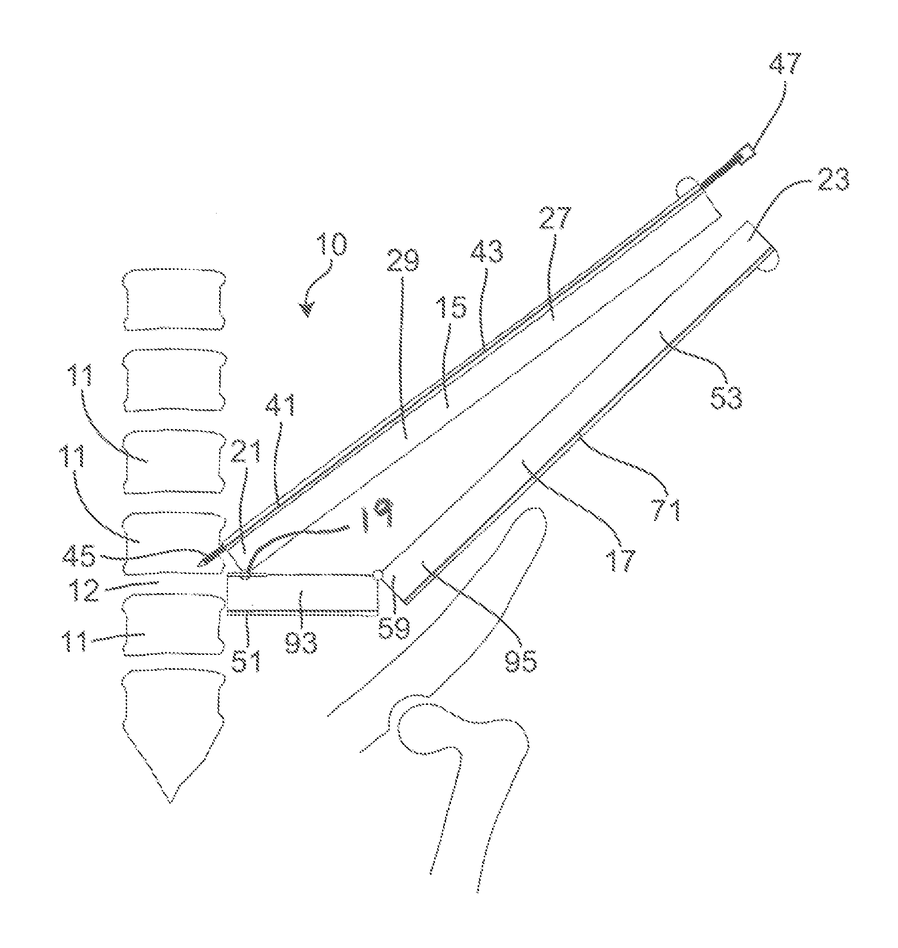
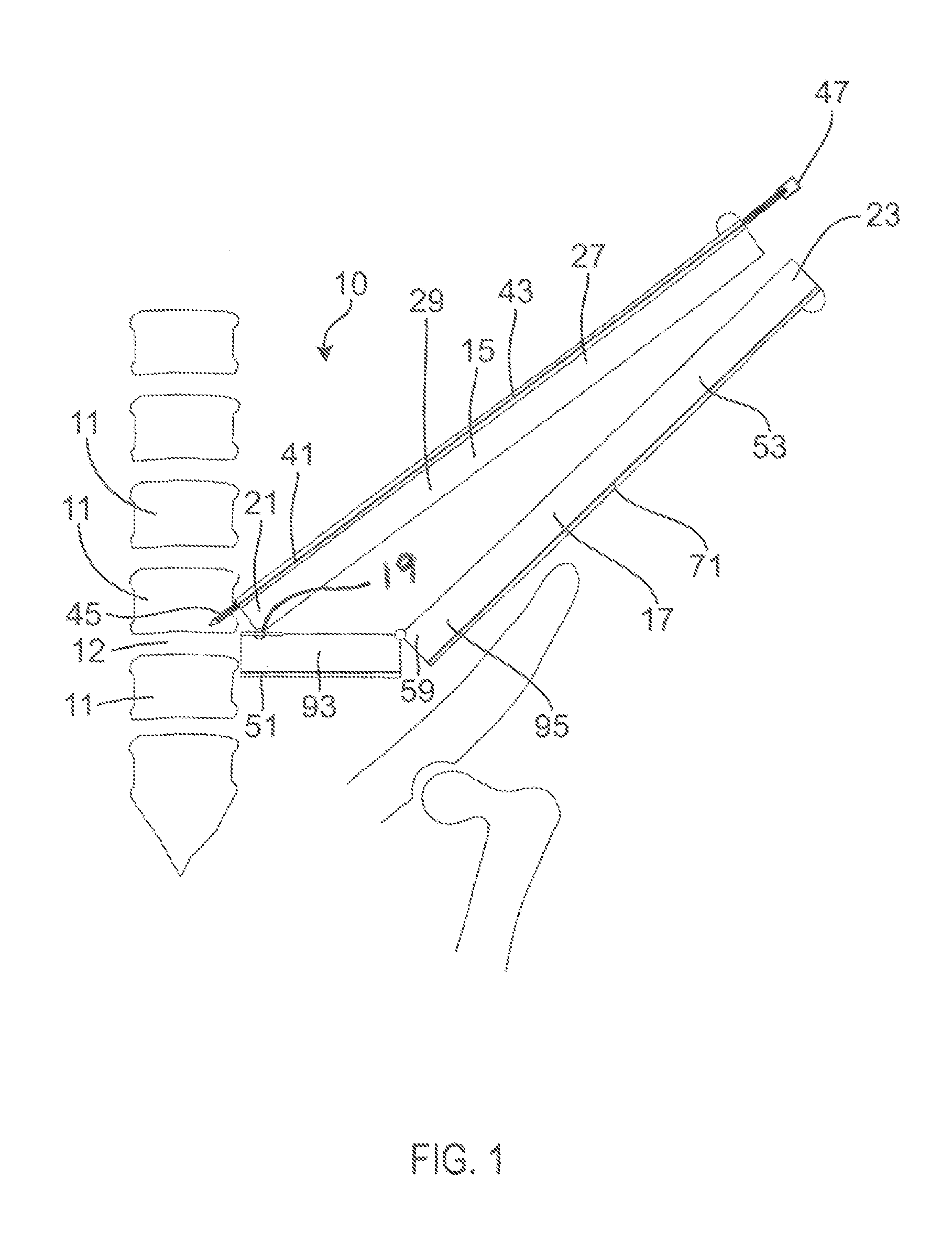
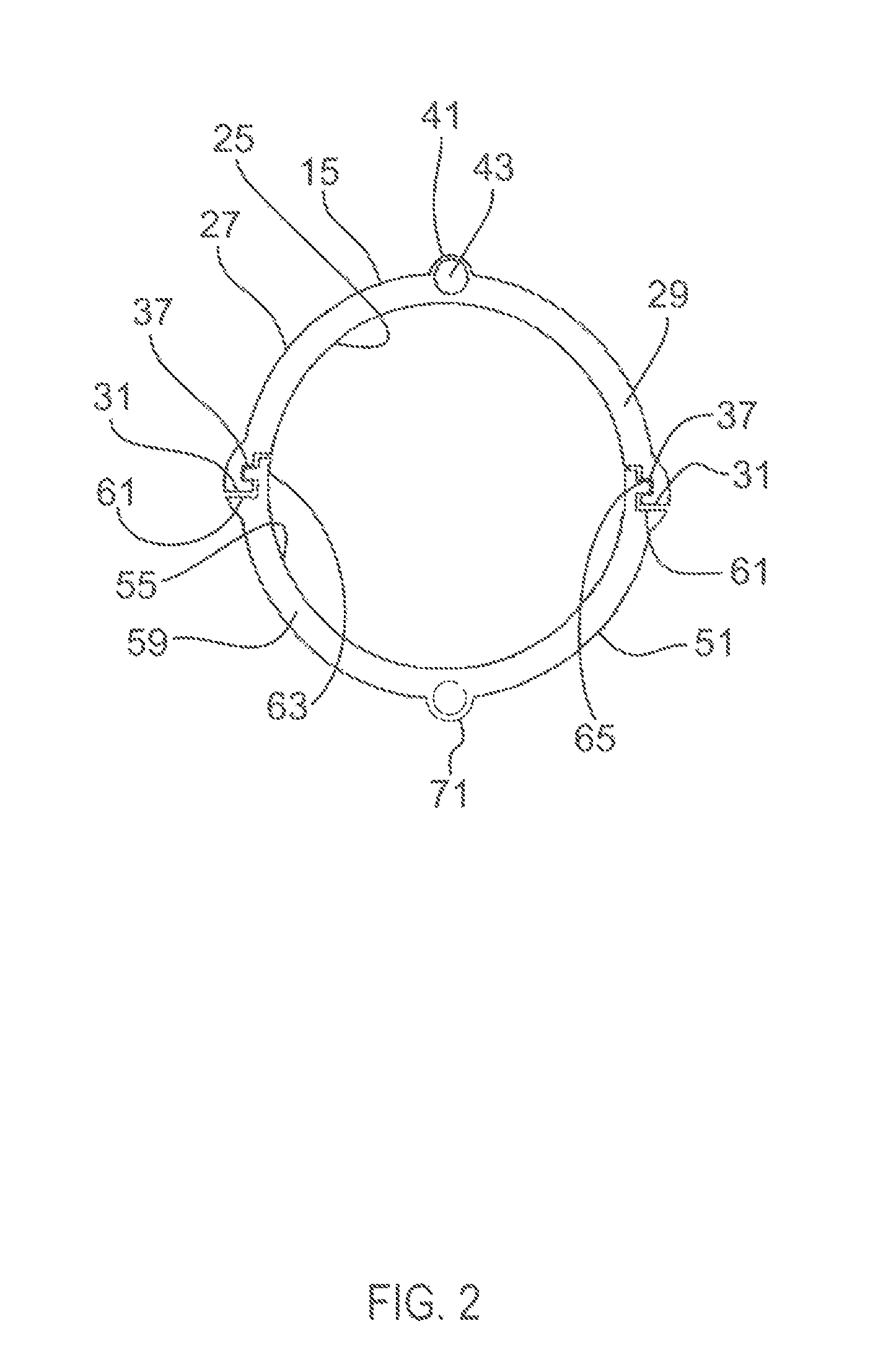
[0012]The proposed retractor blade is designed to function with a number of the currently available retractor systems with only minor modifications to those systems. The retractor blade has a hinge allowing it to flex and thereby allow a lateral approach to the discs at L1-L2 and L4-L5 despite the angle to these discs caused by coming in under the ribs or over the iliac crest. The design would incorporate a channel down the back side containing a pin at the bottom to hold the blade against the vertebral body and is attached to a cable and a rod at the top of the channel. The cable retracts into the center of the lower part of the rod. The upper part of the pin prevents the retractor from flexing as it is inserted in a conventional manner with a straight, non-bendable blade and perhaps other blades over a “K” wire and a series of dilating tubes. Once in proper position, as determined with fluoroscopy and electrical stimulation / EMG, and perhaps with the blades of the retractor somewh...


PUM


Abstract

The proposed retractor blade is designed to function with a number of the currently available retractor systems with only minor modifications to those systems. The retractor blade has a hinge allowing it to flex and thereby allow a lateral approach to the discs at L1-L2 and L4-L5 despite the angle to these discs caused by coming in under the ribs or over the iliac crest.

Description

CROSS REFERENCE TO RELATED APPLICATIONS[0001]This application claims the benefit of U.S. provisional patent application Ser. No. 61 / 075,007 filed Jul. 24, 2012.BACKGROUND OF THE INVENTION[0002]Lateral inter-body fusion has significant advantages over other approaches to the lumbar in that it allows the placement of large inter-body fusion cages that minimize subsidence and allows the correction of scoliosis because contractures of the disc annulus can be released (cut). Currently available retractors for lateral inter-body fusions use two, three or four retractor blades to expose the lateral aspect of the L1-L2, L2-L3, L3-L4 and L4-L5 discs. The L5-S1 disc cannot be currently exposed from a lateral approach. Using the currently available retractor systems, the L1-L2 and L4-L5 discs are often difficult and sometimes impossible to expose for a lateral fusion. The hinged retractor blade and associated equipment are designed to make lateral inter-body cage fusions readily doable at the ...

Claims


Application Information

Patent Timeline
IPC IPC(8): A61B17/12A61B17/02A61B17/88A61B17/70
CPCA61B17/025A61B17/7077A61B17/88A61B17/02A61B17/0293A61B17/3421A61B2017/0256A61B17/3462A61B17/1659A61F2/4611A61F2/4455A61B17/1671A61F2/44A61B17/1604
Inventor O'HARA, THOMAS, E.
Owner OHARA THOMAS E
Learn More