Conveying device for labeling machine

a technology of conveying device and labeling machine, which is applied in the direction of labelling, packaging, transportation and packaging, etc., can solve the problem that the conventional labeling machine is unable to coat the thin shrink film label to the bottom surface of the container,

Active Publication Date: 2016-02-16
HUANG FU CHUAN +1
View PDF7 Cites 0 Cited by
  • Summary
  • Abstract
  • Description
  • Claims
  • Application Information

AI Technical Summary

Benefits of technology

[0006]In view of the aforementioned problem, an objective of the present invention is to provide a conveying device for a labeling machine to convey containers and allow the bottom surface of the containers to be coated by the shrinkable film label when the containers are manufactured, so as to provide containers of improved delicacy and diversities.
[0029]The feeding device feeds in the containers with assistance of the conveying belt provided with top seat fixtures. By engagement of the guiding grooves with a lateral side of the containers guided by the guiding rail, the rotation and increased stroke of the screw feeding rod provides a specific distance to each two adjacent containers, which corresponds to a distance between two adjacent notches on the feeding member. By engagement of notches with another lateral side of the containers, the feeding member rotates to move the containers sequentially to the conveying belt on the conveying belt frame along the guiding rail and place the containers on the top seat fixtures, thereby providing the automation of the conveying device of the present invention.

Problems solved by technology

However, a conventional labeling machine is unable to coat the thin shrink film label to the bottom surface of the container because a conveying belt is utilized to convey the containers in the working process of the labeling machine.

Method used


Image

  • Conveying device for labeling machine
  • Conveying device for labeling machine
  • Conveying device for labeling machine

Examples


Embodiment Construction

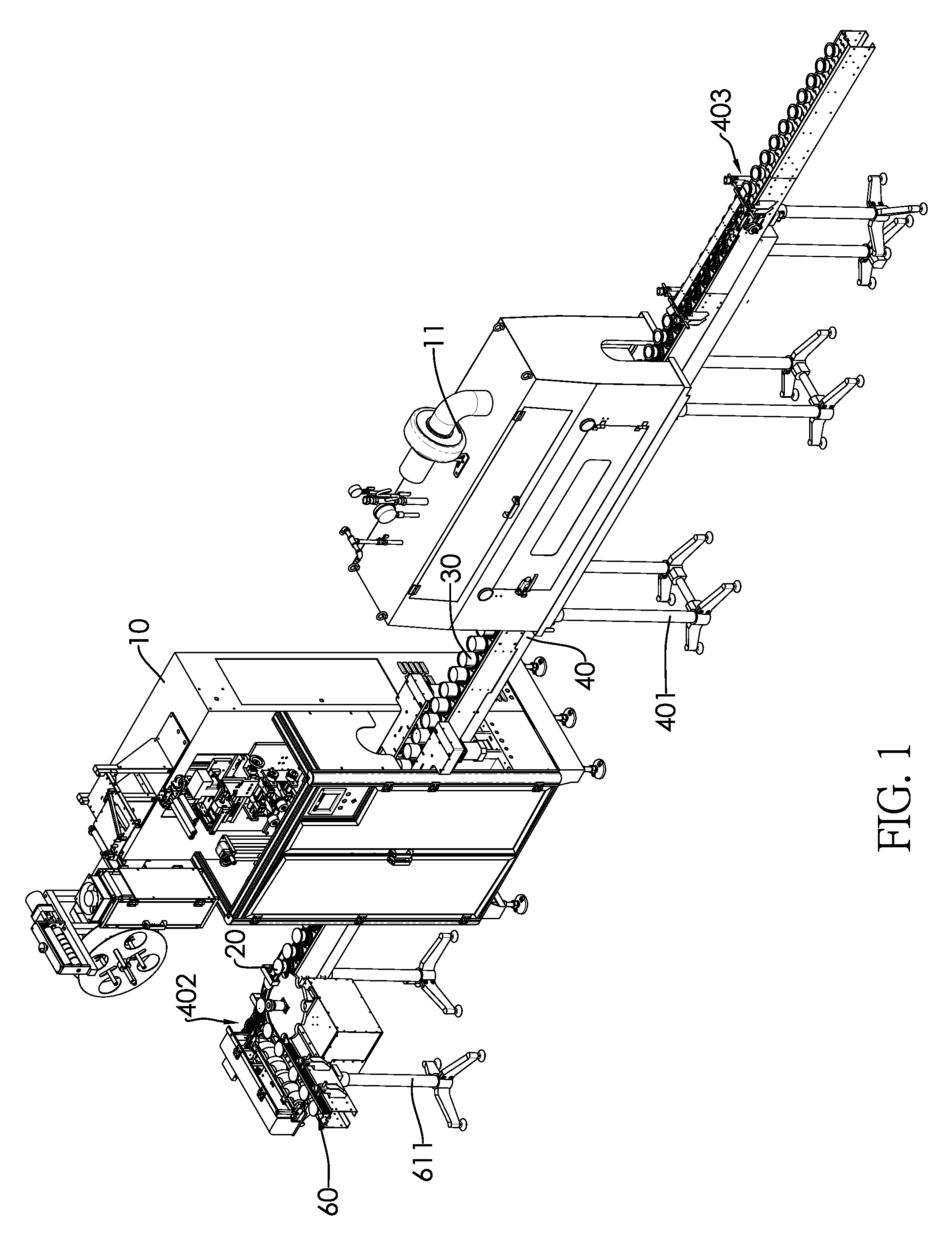
[0039]Referring to FIG. 1, a labeling machine includes a conveying device, a label setting device 10 and heating device 11. The conveying device conveys a plurality of containers sequentially to the label setting device 10 and the heating device 11. The label setting device 10 sets a shrinkable film label 30 on a container 20, and the shrinkable film label 30 is heated by the heating device 11 to be shrunk and coated on the container 20.

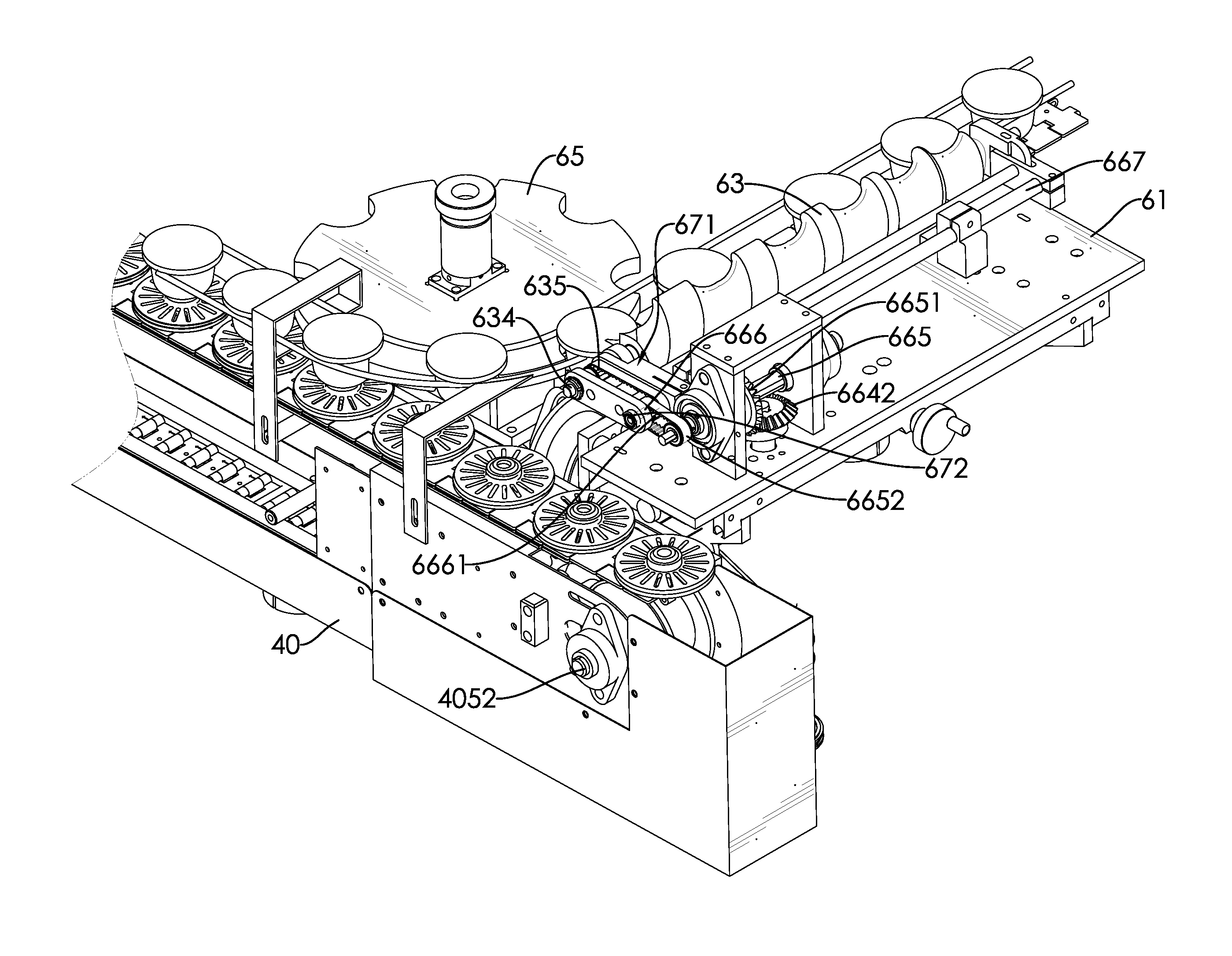
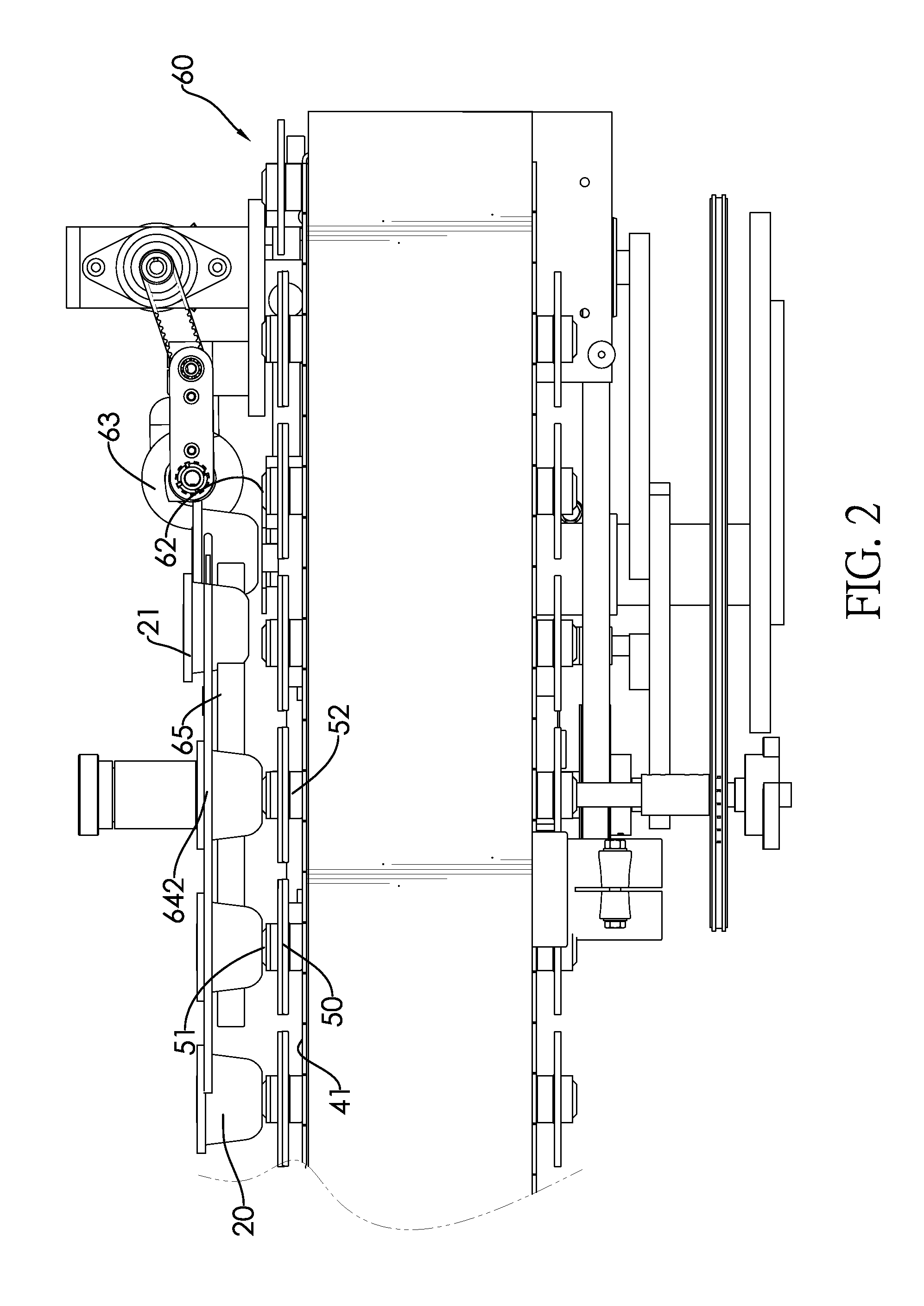
[0040]The present invention provides a conveying device for said labeling machine. Referring to FIGS. 2 and 3, the conveying device includes a conveying belt frame 40, a plurality of top seat fixtures 50 and a feeding device 60.

[0041]The conveying belt frame 40 is an elongated frame supported by a plurality of supporters 401 on a plane. The conveying belt frame 40 has a feed-in end 402 and a feed-out end 403. Referring to FIG. 7, two conveying belts 41 and 42 are disposed on the conveying belt frame 40 in a longitudinal direction of the conveying bel...


PUM

PropertyMeasurementUnit
distanceaaaaaaaaaa
shapesaaaaaaaaaa
shapeaaaaaaaaaa

Abstract

A conveying device for a labeling machine is provided with a conveying belt frame (40), plurality of top seat fixtures (50) and a feeding device (60). A conveying belt (41) is mounted on the conveying belt frame (40). The top seat fixtures (50) are mounted at intervals on the conveying belt (41). A protrusion column (51) is protruded from the top surface of each top seat fixtures (50), so that a space can be formed between the bottom of containers and the top seat fixtures when the containers are mounted on the top seat fixtures. The shrinkable film labels can be set around the lower bottom of the containers after being cut by the labeling machine so that the labels can be shrunk to coat the bottom surface of the containers after being heated. The feeding device (60) cooperates with the conveying belt (41) and the top seat fixtures (50) so that the containers to be processed are conveyed by the feeding device (60) to the conveying belt (41) on the conveying belt frame.

Description

BACKGROUND OF THE INVENTION[0001]1. Field of the Invention[0002]The invention relates to a labeling machine, and in particular to a conveying device for a labeling machine.[0003]2. Description of the Prior Arts[0004]Containers in our daily life such as pudding cups, beverage bottles, cosmetic containers, etc. often have a thin shrinkable film label set around their surfaces for marking or decoration. A thin shrinkable film label is placed on the surface of the container and then heated by a labeling machine so that the thin shrinkable film label can be shrunk to coat the container.[0005]However, a conventional labeling machine is unable to coat the thin shrink film label to the bottom surface of the container because a conveying belt is utilized to convey the containers in the working process of the labeling machine. Referring to FIG. 8, since a container 20 is placed on a conveying belt 70 with a bottom surface of the container 20 contacting the conveying belt 70 when the container...

Claims


Application Information

Patent Timeline
Patent Type & Authority Patents(United States)
IPC IPC(8): B65G29/00B65C9/02B65C3/06B65G37/00B29C63/42B65G17/46
CPCB65G37/00B29C63/423B65C3/065B65C9/02B65G17/46B65G2201/0235
Inventor HUANG, FU-CHUAN
Owner HUANG FU CHUAN
Why Eureka
Try Eureka