Surface element for an aircraft, aircraft and method for improving high-lift generation on a surface element

a surface element and aircraft technology, applied in the direction of airflow influencers, drag reduction, wing lift eficiency, etc., can solve the problems of high recompression, high danger of flow separation, and characteristics and geometric limitations of adjacent ends, so as to achieve effective high lift

Active Publication Date: 2016-03-01
AIRBUS OPERATIONS GMBH
View PDF70 Cites 12 Cited by
  • Summary
  • Abstract
  • Description
  • Claims
  • Application Information

AI Technical Summary

Benefits of technology

[0008]An aspect of the invention proposes a surface element that is adapted for effectively producing high lift essentially without aerodynamic penalties due to a span wise shortened or interrupted leading edge high lift device.

Problems solved by technology

When the high lift devices are deployed the flow characteristics and geometric limitations of the adjacent end faces of the interrupted slat arrangement disturb the lift generation as it becomes inharmonic due to the creation of highly three-dimensional vortical structures in the wake of the end faces.
The occurring suction peak of the unprotected surface element is significantly higher in comparison to leading edge regions without a leading edge high lift device, therefore a higher recompression and higher danger of flow separation occurs.

Method used


Image

  • Surface element for an aircraft, aircraft and method for improving high-lift generation on a surface element
  • Surface element for an aircraft, aircraft and method for improving high-lift generation on a surface element
  • Surface element for an aircraft, aircraft and method for improving high-lift generation on a surface element

Examples


Embodiment Construction

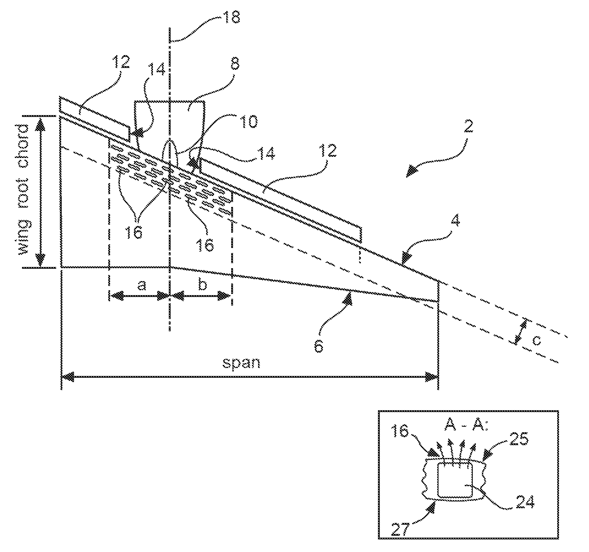
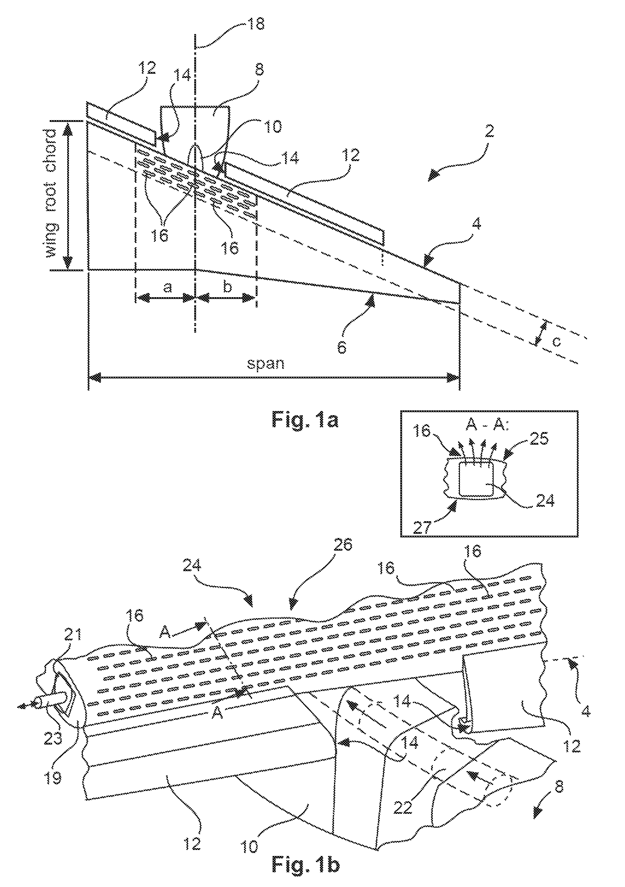
[0034]FIG. 1a shows a schematic view on a wing 2 as a surface element according to the invention. The wing 2 as a surface element has a leading edge 4, a trailing edge 6, and an engine 8 mounted on the underside near the leading edge 4. For supporting the engine 8, a support structure is used which is not depicted in detail herein. Usually, push rods and brackets are used for the introduction of forces and for providing directional stability. The support structure is covered by an aerodynamic pylon 10 that extends from the engine 8 directly to the underside of the wing in a region of the leading edge 4 and can be considered, like the engine 8 itself, an add-on body.

[0035]For reducing the necessary speed for landing or takeoff the aircraft associated with the wing 2, the wing 2 exemplarily comprises slats 12 as high lift devices on the leading edge 4 and additional flaps on the trailing edge, which flaps are not depicted herein. In a region around the engine 8 and the pylon 10, the s...


PUM


Abstract

A surface element, e.g. a wing, of an aircraft includes a leading edge, a high lift device arrangement positioned along the leading edge and at least one add-on body positioned in a leading edge region, wherein the high lift device arrangement is interrupted in the region of at least one add-on body for preventing collision with the add-on body and wherein the surface element includes an arrangement of openings in a region covering the add-on body, which openings are connected to an air conveying device for conveying air through the openings. Thereby an additional flap for harmonizing the flow above a pylon or other add-on body can be eliminated.

Description

CROSS-REFERENCE TO RELATED APPLICATIONS[0001]This application claims the benefit of the filing date of European Patent Application No. 12 162 149.4 filed Mar. 29, 2012 and of U.S. Provisional Patent Application No. 61 / 617,174 filed Mar. 29, 2012, the disclosure of which applications is hereby incorporated herein by reference.TECHNICAL FIELD[0002]The invention relates to a surface element for an aircraft, an aircraft and a method for improving high lift generation on a surface element.BACKGROUND OF THE INVENTION[0003]Commercial aircraft usually comprise wing-mounted engines. For civil use turbofan engines with a high bypass ratio are preferred as they provide a low thrust specific fuel consumption, wherein by enlarging the diameter of a fan section, the bypass ratio of a turbofan engine can be increased. Hence, on one hand, for better fuel efficiency the radial extension of turbofan engines is to be increased and on the other hand the preferred mounting position under a wing strongly...

Claims


Application Information

Patent Timeline
Patent Type & Authority Patents(United States)
IPC IPC(8): B64C21/04B64C21/02B64C9/24B64C21/06
CPCB64C21/025B64C9/24B64C21/02B64C21/04B64C21/06Y02T50/166Y02T50/32Y02T50/30Y02T50/10
Inventor RECKZEH, DANIELGOELLING, BURKHARDLENGERS, MATTHIAS
Owner AIRBUS OPERATIONS GMBH
Why Eureka
Try Eureka