Check patentability & draft patents in minutes with Patsnap Eureka AI!

Stacking bracket

a technology for stowing brackets and heating units, which is applied in the direction of machine supports, lighting and heating apparatuses, heating types, etc. it can solve the problems of increasing the materials and labor costs of storage or transportation of hvac units, and the cost of wood stowing further increases the cost of contractors that install havc units

Active Publication Date: 2016-03-01
LENNOX IND INC
View PDF11 Cites 17 Cited by
  • Summary
  • Abstract
  • Description
  • Claims
  • Application Information

AI Technical Summary

Benefits of technology

[0011]The apparatus and system provided, herein, may, advantageously provide surfaces against which a top HVAC unit may slide, or impact, in response to disturbance forces while resisting dislodgement of the top HVAC unit. The apparatus and system may provide lateral resistance to movement of the top HVAC unit relative the bottom HVAC unit while providing substantially no resistance to substantially vertical movement of the top HVAC unit. Accordingly, the top HVAC unit may be lifted from the bottom HVAC unit without interference from the stacking brackets. Further, the stacking brackets may provide additional features that may aid in locating tie down straps for securing the HVAC unit, or units to a flat surface.

Problems solved by technology

The use of wood crating increases the materials and labor costs related to storage or transport of HVAC units.
The wood crating further increases costs to contractors that install the HAVC units and generates waste that must be disposed of by the contractors or the HVAC unit owners.
The HVAC unit, or stacked HVAC units, may experience disturbance forces during transportation.
The sliding resistance provided by the straps, alone, may not be enough to resist such sliding of the HVAC units during transportation.

Method used


Image

  • Stacking bracket
  • Stacking bracket
  • Stacking bracket

Examples


first embodiment

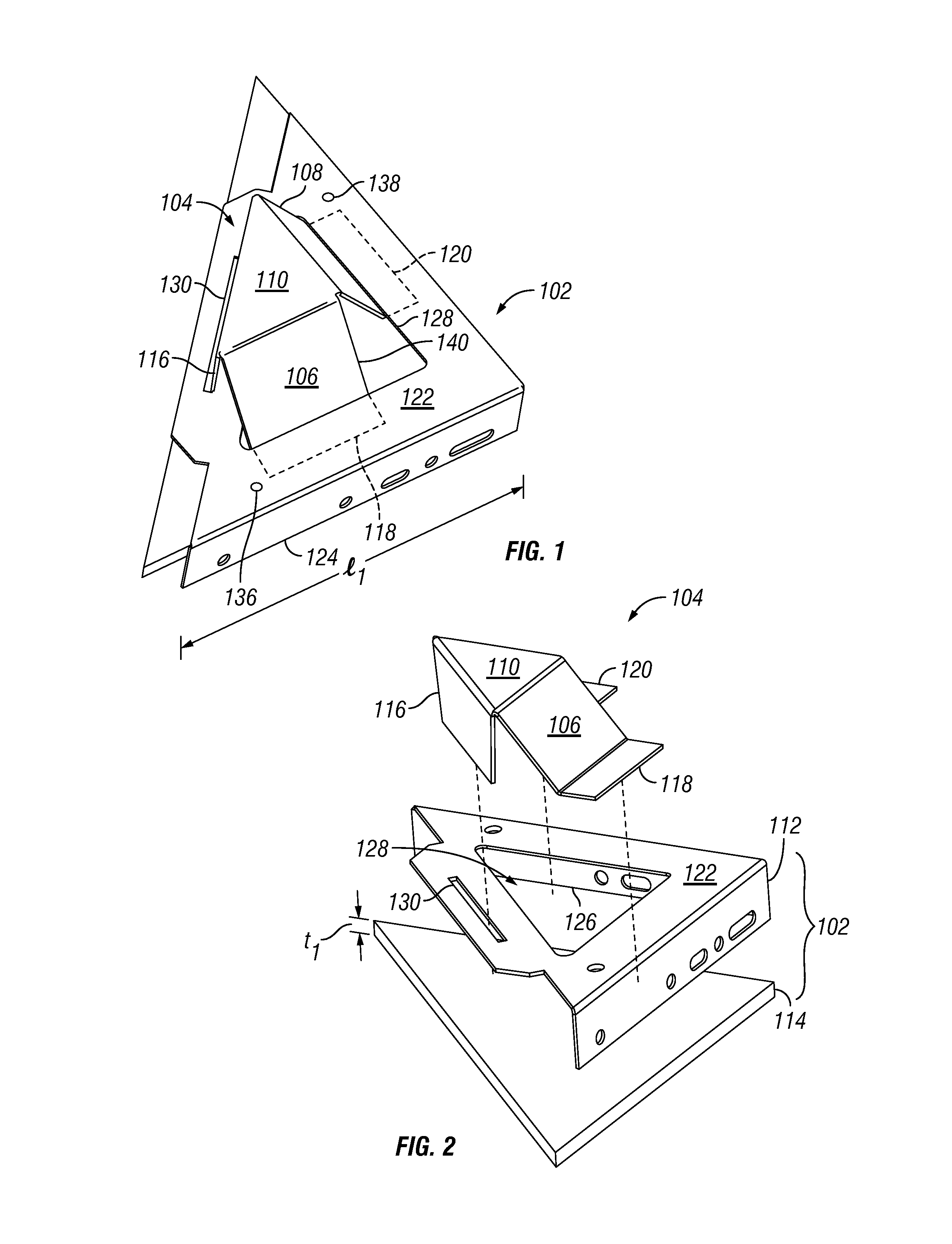
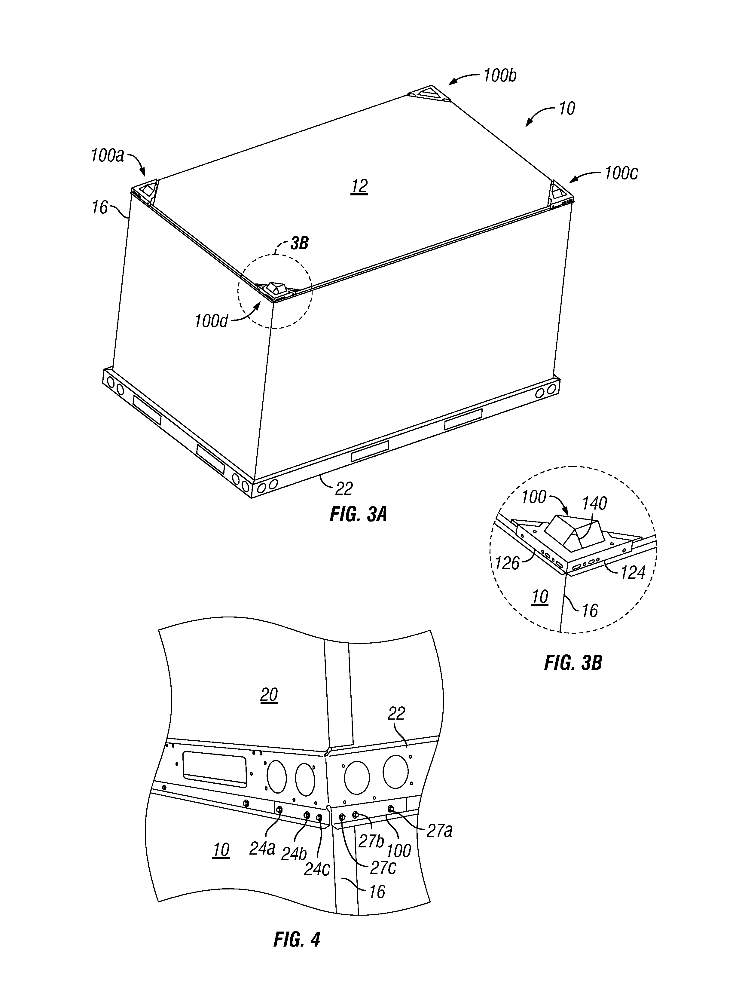
[0039]Referring to FIGS. 1 and 2, in a first embodiment, a first stacking bracket 100 for stacking a top HVAC unit (referred to as a “unit”) on a bottom unit may comprise a base member 102 and a stacking insert 104. The first stacking bracket 100 is configured to be mounted to a top cover 12 (shown in FIG. 3A) of a bottom unit 10. In some embodiments, the first stacking bracket 100 is attached to a corner 16 of the bottom unit 10, as shown in FIGS. 3B and 4.

[0040]As shown in FIG. 1, the first stacking insert 104 may be coupled to the base member 102. The stacking insert 104 may comprise one or more substantially sloped surfaces 106, 108 extending from a top surface 110 of the stacking insert 104 to a top surface 122 of the base member 102, when the base member 102 and stacking insert 104 are coupled and mounted to the bottom unit 10. The sloped surfaces 106,108 may be configured to impede displacement of a top unit 20 that has been stacked on top of the bottom unit 10.

[0041]Referrin...

second embodiment

[0067]FIG. 9 illustrates a stacking bracket for stacking the top unit 20 on the bottom unit 10. A second stacking bracket 200 may replace, as an alternative, the first stacking bracket 100 in the configurations shown in FIGS. 3A and 4.

[0068]Referring to FIG. 9, the second stacking bracket 200 may comprise some similar features as the first stacking bracket 100, shown in FIGS. 1 and 2. Second stacking bracket 200 may comprise a second insert 204 coupled to a second base member 202. In a manner similar to the first stacking bracket 100, the second insert 204 may comprise sloped surfaces 206, 208 inclined relative to a top surface 222 of the base member 202. The second stacking insert 200 may further be used as part of the system shown and described in Figure FIGS. 3A and 4.

[0069]Referring to FIGS. 10 and 11, the top unit 20 may be rocked due to a disturbance force applied to the top unit 20, as may be experienced during transport of the top unit 20. This disturbance force may cause a ...

third embodiment

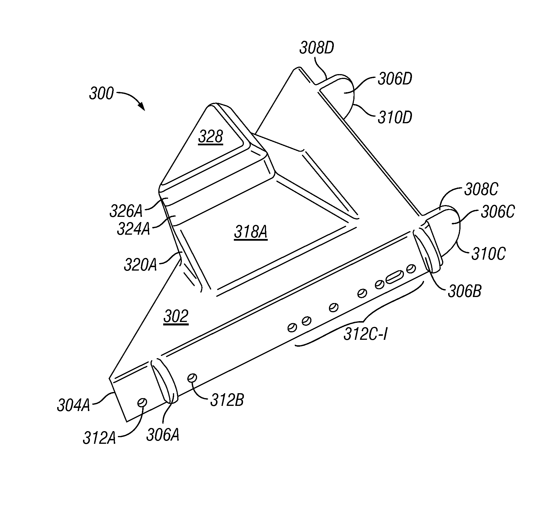
[0099]Referring to FIGS. 17-24, a stacking bracket for stacking the top unit 20 on the bottom unit 10 is shown. The third stacking bracket 300 may be used for stacking a top unit 20 on top of a bottom unit 10 in a manner similar to that described above and in reference to the first stacking bracket 100 and second stacking bracket 200. The third stacking bracket 300 may aid in locating the top unit 20 as it is stacked on the bottom unit 10, and may, further, resist sliding movement of the top unit 20 relative to the bottom unit 10 in response to disturbance forces. Further, the third stacking bracket 300 may be used as part of a system similar to that shown and described in FIGS. 3A and 4 in reference to the first stacking bracket 100 and the second stacking bracket 200.

[0100]As described herein, the third stacking bracket 300 may comprise, generally, a base member portion and a raised insert portion. The raised insert portion may further comprise a ramp section and a vertical extens...


PUM


Abstract

The present invention provides an apparatus for supporting stacking of a top heating, ventilation, and air conditioning (HVAC) unit on top of a bottom HVAC unit. The apparatus includes a base member configured to mount to a top cover of the bottom HVAC unit. The base member comprises an upper base portion with a top surface configured to receive at least a portion of a base rail of the top HVAC unit. The apparatus further comprises a stacking insert extending away from the base member. The stacking insert has one or more sloped surfaces extending above the top surface of the upper base portion. The top surface extends from a base of the one or more sloped surfaces in a plane substantially parallel to the top cover, when the base member is mounted to the top cover of the bottom HVAC unit.

Description

CROSS-REFERENCE TO RELATED APPLICATIONS[0001]This application is a continuation in part and claims the benefit of the filing date of co-pending U.S. patent application Ser. No. 14 / 022,174, filed Sep. 9, 2013, and claims priority therefrom. The contents of the prior application are hereby incorporated by reference with the same effect as if fully set forth herein.FIELD OF THE INVENTION[0002]The present invention relates to stacking of heating, ventilation, and air conditioning units and, more particularly, to devices to support stacking heating, ventilation, and air conditioning units.DESCRIPTION OF RELATED ART[0003]Heating, ventilation, and air conditioning (HVAC) units are typically transported in an enclosed van or on a flatbed. Wood crating members mounted around the HVAC unit provide protection to the surfaces and internal components of the HVAC unit when the HVAC units are bumped, jostled, or otherwise disturbed during transport.[0004]The HVAC units may be stacked with a top HV...

Claims


Application Information

Patent Timeline
Patent Type & Authority Patents(United States)
IPC IPC(8): F16M1/00F24F13/32B65D6/00B65D67/02F16M11/00B65D69/00F16M3/00F16M5/00F16M7/00F16M9/00
CPCB65D69/00B65D7/00B65D67/02F24F13/32
Inventor WYNNICK, DAVID, MICHAELWEIGEL, TIMOTHY, GRANTWHITESIDES, CHRISTOPHER
Owner LENNOX IND INC
Features
  • R&D
  • Intellectual Property
  • Life Sciences
  • Materials
  • Tech Scout
  • Unparalleled Data Quality
  • Higher Quality Content
  • 60% Fewer Hallucinations
Learn More