Fan

a technology of fan and fan body, which is applied in the direction of leakage prevention, vehicle components, motors, etc., can solve the problems of undesirable increase in the transmission of vibrations from the motor housing to the casing, and reduce the extent of vibrations

Inactive Publication Date: 2016-05-03
DYSON TECH LTD
View PDF451 Cites 3 Cited by
  • Summary
  • Abstract
  • Description
  • Claims
  • Application Information

AI Technical Summary

Benefits of technology

[0006]The present invention provides a fan comprising a casing having an air inlet and an air outlet, an impeller housing mounted on an annular seat located within the casing, an impeller located within the impeller housing for generating an air flow along a path extending from the air inlet to the air outlet through the impeller housing, a motor housing connected to the impeller housing, a motor located within the motor housing for driving the impeller, an annular seal in sealing engagement with the impeller housing and the seat, and at least one resilient support located between the impeller housing and the seat for reducing the compressive load applied to the annular seal.
[0007]The fan assembly thus comprises both an annular seal and at least one resilient support located between the impeller housing and a seat upon which the impeller housing is mounted. The compression of the annular seal between the impeller housing and the seat forms an air tight seal which prevents air from leaking back towards the air inlet of the casing along a path extending between the casing and the impeller housing, and so forces the pressurized air flow generated by the impeller to pass to the air outlet of the casing.
[0008]The annular seal is preferably a foam annular seal. Forming the annular seal from a foam material, as opposed to an elastomeric or rubber material, can reduce the transmission of vibrations to the casing through the annular seal. The resilient support(s) are also disposed between the impeller housing and the seat so as to bear some of the combined weight of the impeller housing, impeller, motor housing and motor, and thereby reduce the compressive load acting on the annular seal. This reduces the extent of the deformation of the annular seal; an excessive compression of the annular seal between the impeller housing and the seat could result in an undesirable increase in the transmission of the vibrations from the motor housing to the casing through the annular seal.
[0010]In addition to forming an air-tight seal between the impeller housing and the casing, the annular seal can also provide a damping action for reducing the vibration of the resilient support(s) during use of the fan assembly, and so reduce the transmission of the vibrations from the motor housing to the casing through the resilient support(s).

Problems solved by technology

This reduces the extent of the deformation of the annular seal; an excessive compression of the annular seal between the impeller housing and the seat could result in an undesirable increase in the transmission of the vibrations from the motor housing to the casing through the annular seal.

Method used


Image

  • Fan
  • Fan
  • Fan

Examples


Embodiment Construction

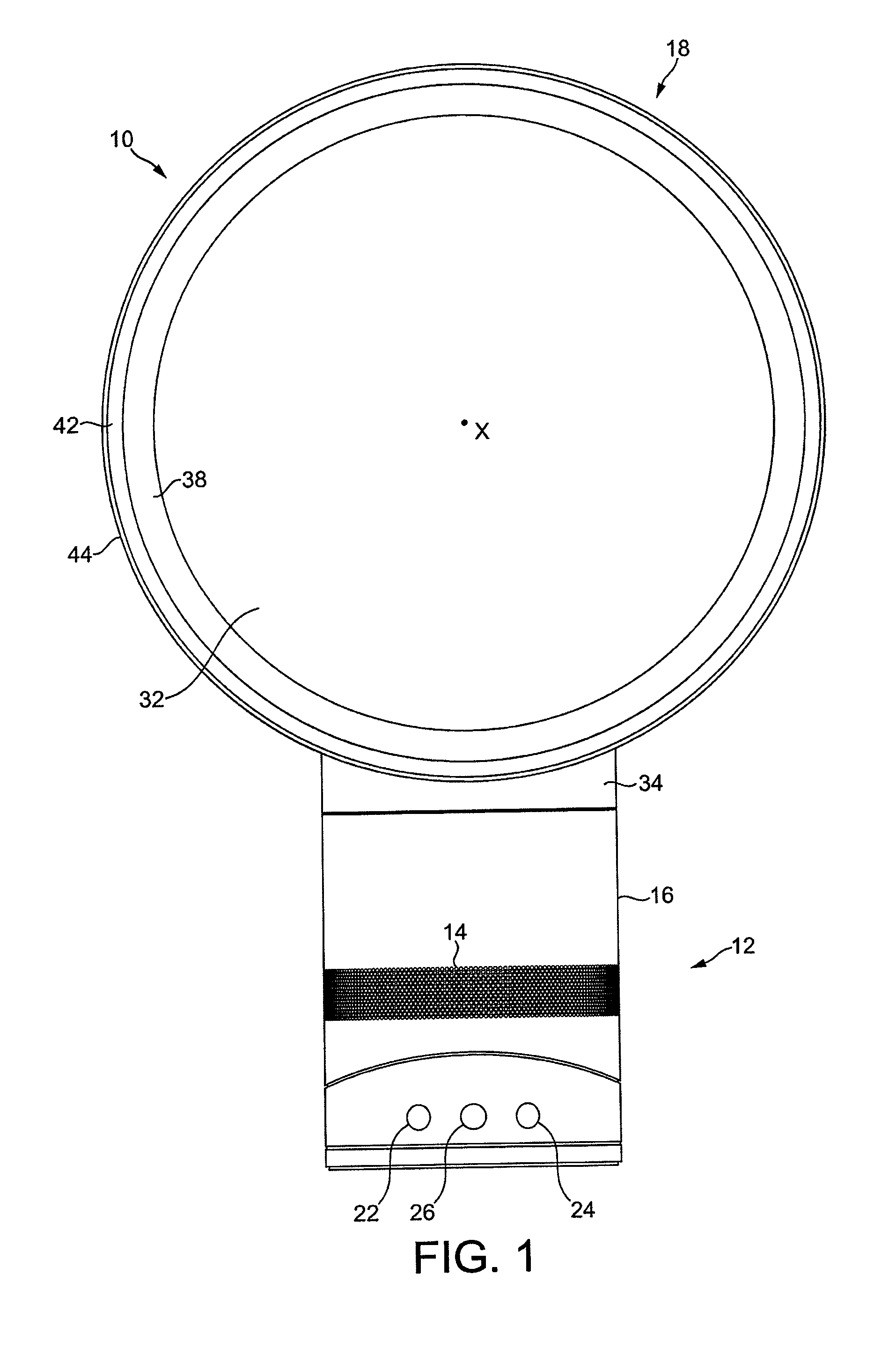
[0024]FIG. 1 is a front view of a fan 10. The fan comprises a body 12 having an air inlet 14 in the form of a plurality of apertures formed in the outer casing 16 of the body 12, and through which a primary air flow is drawn into the body 12 from the external environment. An annular nozzle 18 having an air outlet 20 for emitting the primary air flow from the fan 10 is connected to the body 12. The body 12 further comprises a user interface for allowing a user to control the operation of the fan 10. The user interface comprises a plurality of user-operable buttons 22, 24 and a user-operable dial 26.

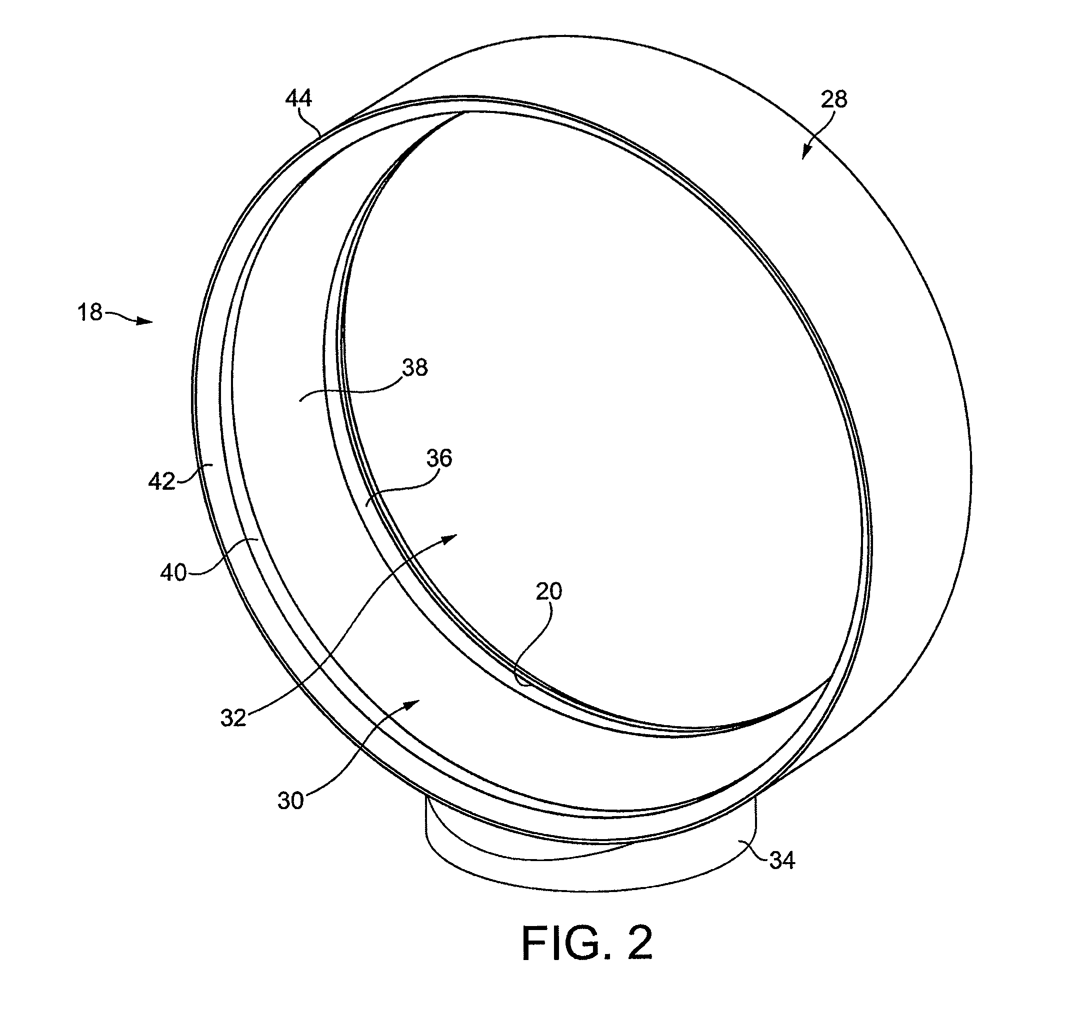
[0025]As also shown in FIG. 2, the nozzle 18 comprises an annular outer casing section 28 connected to and extending about an annular inner casing section 30. The annular sections 28, 30 of the nozzle 18 extend about and define an opening 32. Each of these sections may be formed from a plurality of connected parts, but in this embodiment each of the outer casing section 28 and the inner ca...


PUM


Abstract

A fan includes an outer casing having an air inlet and an air outlet, and an impeller housing located within the casing. An impeller is provided within the impeller housing for generating an air flow along a path extending from the air inlet to the air outlet through the impeller housing. A motor for driving the impeller is located within a motor housing connected to the impeller housing. A foam annular seal is located between the impeller housing and a seat to inhibit the leakage of air between the impeller housing and the casing. A plurality of resilient supports is provided between the impeller housing and the seat to reduce the load on the annular seal.

Description

REFERENCE TO RELATED APPLICATIONS[0001]This application claims the priority of United Kingdom Application No. 1200899.1, filed Jan. 19, 2012, the entire contents of which are incorporated herein by reference.FIELD OF THE INVENTION[0002]The present invention relates to a fan. Particularly, but not exclusively, the present invention relates to a floor or table-top fan, such as a desk, tower or pedestal fan.BACKGROUND OF THE INVENTION[0003]A conventional domestic fan typically includes a set of blades or vanes mounted for rotation about an axis, and drive apparatus for rotating the set of blades to generate an air flow. The movement and circulation of the air flow creates a ‘wind chill’ or breeze and, as a result, the user experiences a cooling effect as heat is dissipated through convection and evaporation. The blades are generated located within a cage which allows an air flow to pass through the housing while preventing users from coming into contact with the rotating blades during ...

Claims


Application Information

Patent Timeline
Patent Type & Authority Patents(United States)
IPC IPC(8): F04D29/42F04D25/08F04D29/60F04D29/08F04D29/66F04F5/16F01D11/00F01D25/00
CPCF04D29/4226F01D11/005F01D25/00F04D25/08F04D29/083F04D29/601F04D29/668F04F5/16B60H1/12F04D29/16F04D29/42F04D29/66
Inventor ATKINSON, ANTOINE FRANCOIS
Owner DYSON TECH LTD
Why Eureka
Try Eureka